


9*8 Electrical system
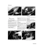
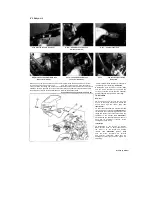
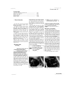
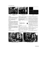
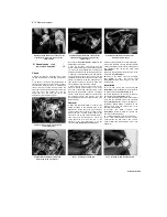
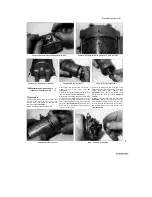
10.2a Tail light wiring connector (arrowed)
-
TRX models
10 Tail light assembly
-
removal and installation
Removal
1
On TDM and TRX models remove the side
covers (see Chapter 8). On XTZ models open
the storage compartment cover behind the seat
and remove the cover
(see illustration 9.1).
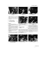
2
On TRX and XTZ models, disconnect the tail
light wiring connector
(see illustrations).
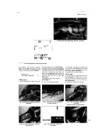
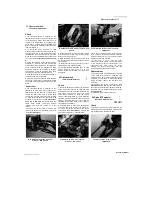
3
Unscrew the nuts securing the tail light
assembly to either the side cover assembly
(TDM models) or the frame (TRX and XTZ
models) and carefully remove it noting how it
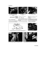
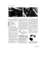
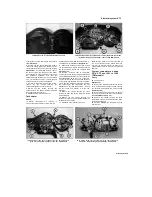
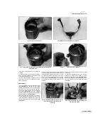
10.3a Tail light assembly nuts (arrowed) -
TDM models
10.2b Tail light wiring connector (arrowed) -
XTZ models
fits
(see illustrations).
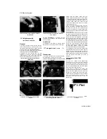
If required, turn the
bulbholders anti-clockwise and withdraw them
from the tail light.
Installation
4 Installation is the reverse of removal. Check
the operation of the tail light and the brake light.
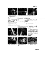
11 Turn signal circuit
- check %>
Flasher relay
1 The battery provides power for operation of the
turn signal lights, so if they do not operate,
10.3b Tail light assembly nuts (arrowed)
-
XTZ
models
always check the battery voltage first. Low
battery voltage indicates either a faulty battery
or a defective charging system. Refer to Section
3 for battery checks and Sections 30 and 31 for
charging system tests. Also, check the fuse
(except XTZ models) (see Section 5) and the
switch (see Section 19).
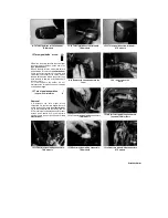
2 Most turn signal problems are the result of a
burned out bulb or corroded socket. This is
especially true when the turn signals function
properly in one direction, but fail to flash in the
other direction. Check the bulbs and the sockets
(see Section 12).
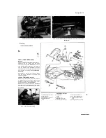
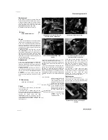
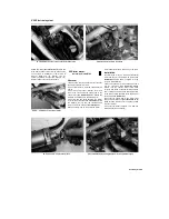
3 The relay is mounted under the seat on TDM
and TRX models, and behind the fairing on XTZ
models
(see illustrations).
Remove the seat or
fairing for access (see Chapter 8). If the bulbs
and sockets are good, check for voltage at the
turn signal relay brown wire (brown/red on 1997-
on UK models) with the ignition ON. If no voltage
is present, using the appropriate wiring diagram
at the end of this Chapter check the wiring
between the relay and the ignition (main) switch.
On 1999 TDM models, if there's no voltage
check the hazard relay as described below.
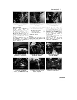
4 If voltage was present, check for voltage at the
relay brown/white wire with the ignition ON. If no
voltage is present, renew the relay. If voltage is
present, check the wiring between the relay, turn
signal switch and turn signal lights for continuity.
Turn the ignition OFF when the check is
complete.
Hazard relay (1999 TDM
models)
5
If there's no voltage at the flasher relay
brown/red wire (see Step 3) check for voltage at
the hazard relay brown wires with the ignition
ON. If no voltage is shown check the signal fuse
and the wiring between the fuse and hazard
relay for a break or bad connection.
6 Also check for voltage at the hazard relay
blue/red wire with the ignition ON; if no voltage is
shown check the hazard fuse and the wiring
between the hazard fuse and hazard relay.
Finally check the brown/red wire from the hazard
relay to the flasher relay for a break or bad
connection. If the fault still exists, renew the
hazard relay.
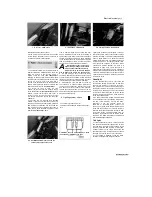
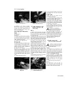
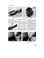
11.3a Turn signal relay (arrowed) - TDM
models
11.3b Turn signal relay (A), starter circuit
cut-off relay (B) - TRX models
■
A
■
1
2^t i^ioi
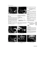
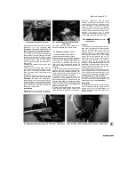
11.3c Turn signal relay (arrowed) -
models
Scaned by Stalker
I
XTZ
Содержание XTZ750
Страница 174: ...UNREGISTERED VI ScanedbyStalker UNREGISTERED VI ...
Страница 207: ...Wiring diagrams 9 29 _____Scaned by Stalker 5 l 6o Cxj fi I JICM ...
Страница 208: ...UNREGISTERED VI 9 30 Wiring diagrams UNREGISTERED VERSION 01 ONREGISTEREDVI Scaned by Stalker ONREGISTERED VERSION 0 ...
Страница 209: ...I UNREGISTERED VI Wiring diagrams 9 31 ____ Scaned by Stalker UNREGISTERED VERSION OF PICTURE DESK ...
Страница 210: ...9 32 Wiring diagrams Scaned by Stalker ...
Страница 211: ...XTZ750 gauge Starter circuit Neutral Starter cut off relay switch rnotor ...


