Engine, clutch and transmission 2»23
91
Jr **-*"
1
%/
V
2k
/ .,■
■>: j
I A
^A ®J
^
•gC^vT
' tJ/^k
/^MsR^
!
/
fcV
M
^3^r~~
s
........... .--
>^B|
*Sf
;;
.*>jOm^'
prr
^
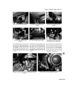
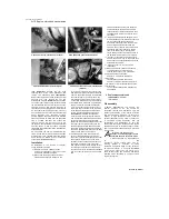
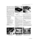
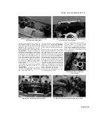
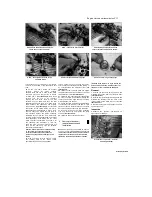
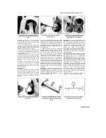
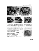
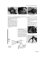
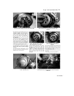
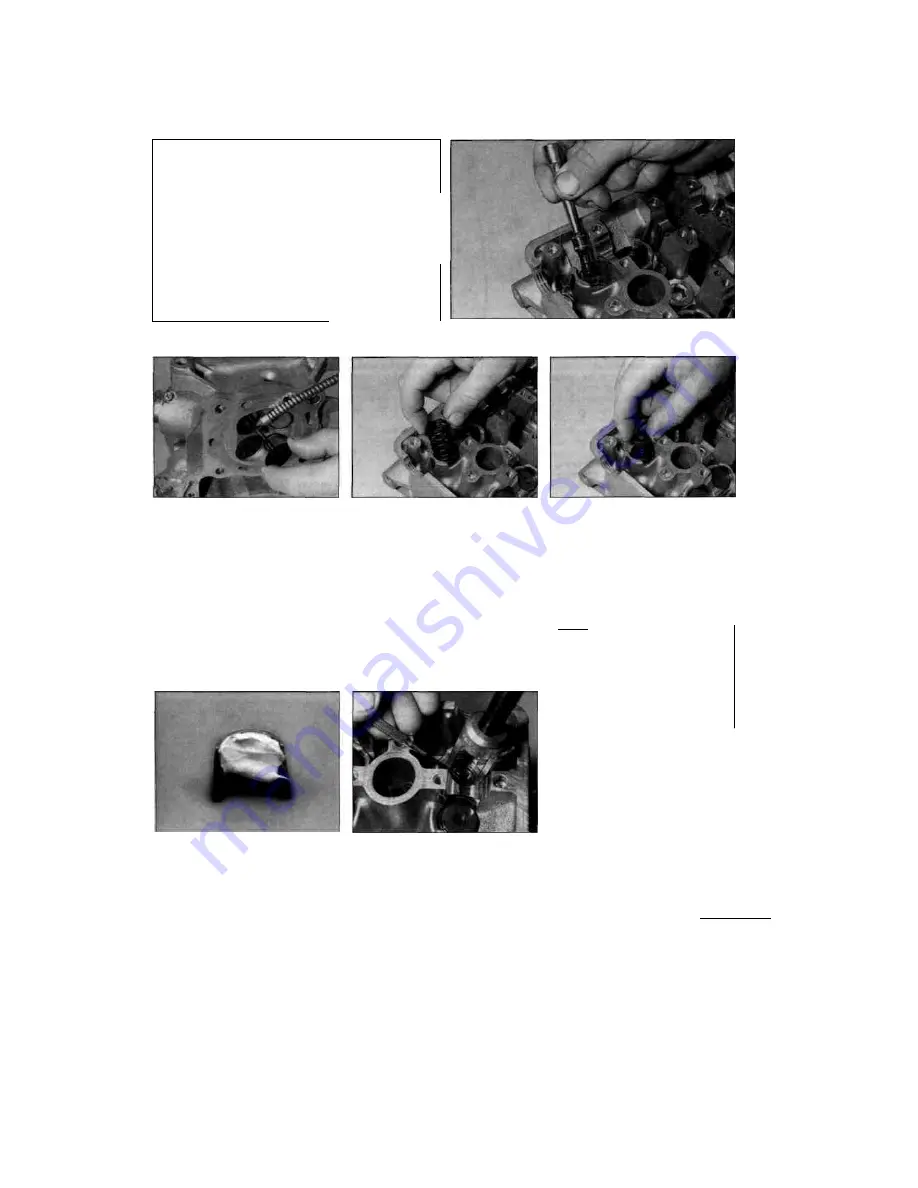
12.25a Fit the spring seat...
12.25b ... then press the valve stem seal into position using a
suitable deep socket
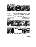
12.26a Lubricate the stem and slide the
valve into its correct location
in the cylinder head, with its shouldered side up
so that the spring fits into it, then install new
valve stem seals on each of the guides
(see
illustrations).
Use an appropriate size deep
socket to push the seals over the end of the
valve guide until they are felt to clip into place.
Don't twist or cock them, or they will not seal
properly against the valve stems. Also, don't
remove them again or they will be damaged.
26 Coat the valve stems with molybdenum
disulphide grease, then install one of them into
its guide, rotating it slowly to avoid damaging the
seal
(see illustration).
Check
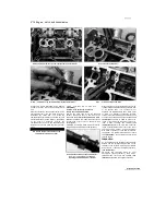
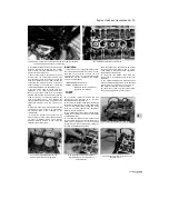
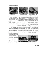
12.27a A small dab of grease will help to
keep the collets in place on the valve while
the spring is released
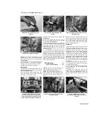
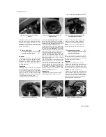
12.26b Fit the valve spring with its closer-
wound coils facing down.
..
that the valve moves up and down freely in the
guide. Next, install the spring, with its closer-
wound coils facing down into the cylinder head,
followed by the spring retainer, with its
shouldered side facing down so that it fits into
the top of the spring
(see illustrations).
27
Apply a small amount of grease to the collets
to help hold them in place as the pressure is
released from the springs
(see illustration).
Compress the springs with the valve spring
compressor
and
install
the
collets
(see
illustration).
When compressing the spring,
depress them only as far as is
12.27b Compress the spring and install
the collets, making sure they locate in the
groove
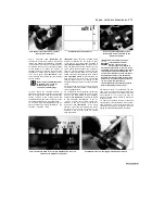
14.26c ... then fit the spring retainer
absolutely necessary to slip the collets into place.
Make certain that the collets are securely locked
in their retaining grooves. 28 Support the cylinder
head on blocks so the valves can't contact the
workbench top, then very gently tap each of the
valve stems with a soft-faced hammer. This will
help seat the collets in their grooves.
fffffflgjl
Check for proper sealing of
""J""
the
valves by pouring
a
HlRIT
small amount of
solvent into
----------
each
of the valve ports. If
the solvent leaks past any valve into the
combustion chamber area the valve
grinding operation on that valve should be
repeated.
13 Cylinder block
-removal,
inspection and installation
Note:
The cylinder block can be removed
with the engine in the frame.
Removal
1 Remove the cylinder head (see Section 10).
2 Unscrew the bolts securing the coolant hose
union to the front of the block and
Staned by Stalker
1
Содержание XTZ750
Страница 174: ...UNREGISTERED VI ScanedbyStalker UNREGISTERED VI ...
Страница 207: ...Wiring diagrams 9 29 _____Scaned by Stalker 5 l 6o Cxj fi I JICM ...
Страница 208: ...UNREGISTERED VI 9 30 Wiring diagrams UNREGISTERED VERSION 01 ONREGISTEREDVI Scaned by Stalker ONREGISTERED VERSION 0 ...
Страница 209: ...I UNREGISTERED VI Wiring diagrams 9 31 ____ Scaned by Stalker UNREGISTERED VERSION OF PICTURE DESK ...
Страница 210: ...9 32 Wiring diagrams Scaned by Stalker ...
Страница 211: ...XTZ750 gauge Starter circuit Neutral Starter cut off relay switch rnotor ...

