For Service Engineer
Service Information
SI1705004E-00=SIGMA-G5SII Service Manual
138/273
4.6. Component Recognition Camera Unit Change
4.6.1. Removal Procedure for the Component Recognition Camera Unit
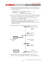
(After the change, perform the teaching operations for the recognition lighting related
items.)
(1)
Shut down the machine and turn off the power breaker.
(2)
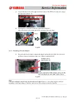
Remove the two set bolts on the both sides of the component recognition camera.
(3)
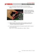
Disconnect all the connectors in the component recognition camera unit.
Fig.D39
(4)
Remove the component recognition camera unit from the machine body.
4.6.2. Attachment Procedure for the Component Recognition Camera Unit
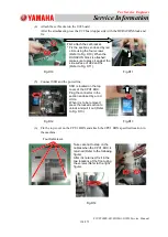
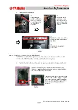
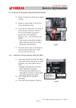
Remove the two bolts in the support section of the
component recognition camera (Refer to Fig. D39).
Remove all the following connectors.
(1) Lighting for the Reference Mark (Base Mark)
(2) Front Lighting
(3) Camera Cable
(4) Main Body Lighting
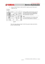
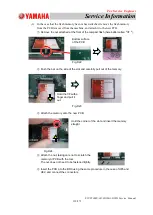
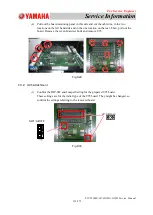
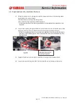
(1) Press the component recognition camera
unit against the pilot pin.
(2) Fix the both sides of the camera unit with
two bolts, keeping the condition that the
unit is pressed against the pilot pin.
* Press the camera based on the right rear
reference and fix, referring to the lower
left photo.
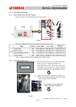
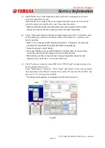
(3) Connect each of the lighting cable,
reference mark, front lighting and camera
cables.
* After connecting the connectors, bind the
cable using cable fies.
Fig.D40

