For Service Engineer
Service Information
SI1705004E-00=SIGMA-G5SII Service Manual
122/273
(3)
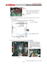
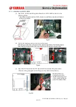
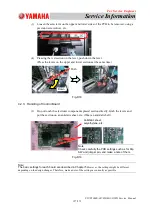
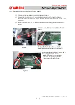
Remove any cable with the power connector (in the locations with CN No., in the
following figure).
After disconnecting the connectors, remove U92 (Frame Grabber).
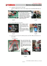
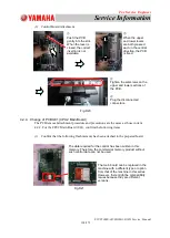
(4) Remove
the six setscrews for CPU1 and then, remove the board.
Four
Setscrews
One
Setscrew
U92 Frame Grabber
*Use an antistatic sheet, etc.
Six Setscrew
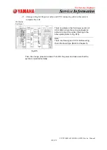
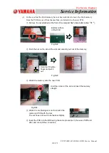
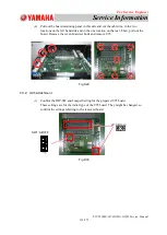
* When U91 is to be removed
from the locations each shown
by a red circle in the left figure,
press the connector section
arranged in front of the board to
slide as shown in the following
figure.
Fig. D6
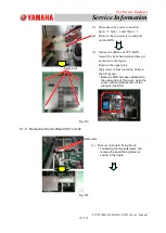
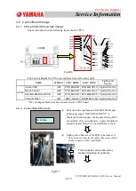
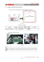
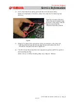
(2) Remove the set bracket. Remove four
setscrews shown in the left figure.
Then, remove the setscrew at the tip
end of U92.
Fig. D5

