For Service Engineer
Service Information
SI1705004E-00=SIGMA-G5SII Service Manual
169/273
4.12. Maintenance in Trouble Occurrence (Mechanism)
4.12.1. High-speed Head Change
4.12.1.1. Removal of Electric Wiring, etc.
(1) House all the nozzles.
(2) Shut down the machine and turn OFF the breaker.
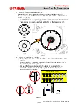
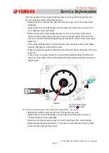
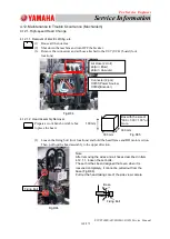
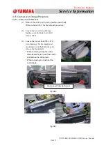
(3) Remove the connectors and air hose attached to the U07 (UC41) board (four
locations).
4.12.1.2. Head Assembly Removal
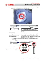
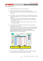
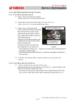
Prepare a work bench or stable box
to place the head.
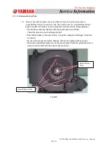
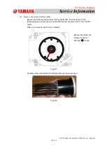
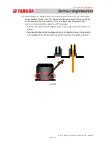
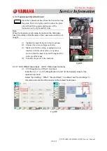
(1) Loosen the fixing bolt (four locations) and hold the head frame and DD motor section.
Then, pull out the head assembly to the upper direction.
Fig.D85
Fixing Bolt
Base
Fig.D84
Connector (2 pcs)
X0701(Power Source)
X0702(Encoder)
Air Hose (2 Unit)
6(Air / Blow)
8(Air / Vacuum)
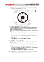
Fig.D86
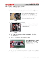
Fixing Bolt
Note:
After removing the wires and air hoses described in Item
4.12.1.1, loosen the set bolts.
The set bolt has been designed that even when it is
loosened completely, it cannot be pulled out from the
base.(Fig.D86)
Pull out the head taking care of the side view camera.
300 mm
300 mm
100 mm
Box with the size of
"300 × 300 × 100" or
more.


