For Service Engineer
Service Information
SI1705004E-00=SIGMA-G5SII Service Manual
153/273
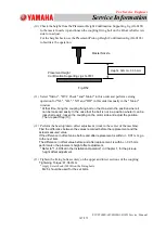
4.11. Nozzle Shaft Removal and Attachment (Single Unit)
4.11.1. Nozzle Shaft Removal and Attachment (Single Unit)
4.11.1.1. Nozzle Shaft Removal (Single Unit)
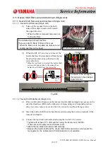
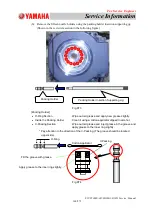
(1)
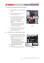
Take out the vacuum filter on the both
sides of the subject nozzle shaft, toward
the upper direction.
* When the filter is removed, take care not
to drop the filter.
(2) When the M1. 6L3 screws are removed, the
nozzle shaft section is separated from the top
block section and can be pulled out in the
lower direction.
*
When the top block is removed, the nozzle shaft
section will pop out due to the spring force
behind it, so hold it from the lower side.
Fig.D64
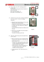
4.11.1.2. Nozzle Shaft Attachment (Single Unit)
(1)
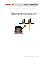
Wipe out dirt and old grease on the removed nozzle shaft and apply new grease on the
specified locations (Perform the ultrasonic cleaning using water depending on how
dirty it is). Also, remove excessive Screw Lock on the top block fixing section.
(2)
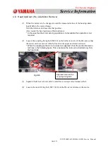
Insert the nozzle shaft from the head lower section using the reverse procedure of the
removal and hold it.
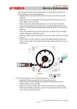
(3)
Connect the top block and nozzle shaft using the two M1. 6L3 screws.
* Tighten with torque of 7.5 cNm and fix it using the Screw Lock (1401B).
(Take care not to apply too much Screw Lock).
* Attach the top block and nozzle shaft vertically.
* Because the nozzle shaft and the nozzle shaft holder are sold as a set (serial No.
management), the replacement of individual parts is not available.
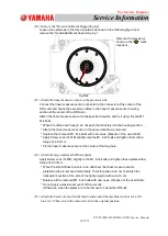
Nozzle Shaft Unit Section
The indicated point shows the filter.
There are total 15 filters. Pull all of them out.
* When the filters are to be pulled out, take care not
to drop any filter on the head.
Fig.C61
Fig.D63
M1.6×
L2
As shown in the left figure,
the top block is fixed using a
single terminal.


