For Service Engineer
Service Information
SI1705004E-00=SIGMA-G5SII Service Manual
124/273
(4)
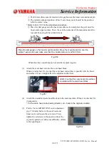
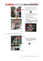
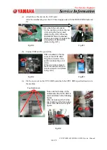
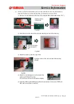
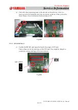
Attach the set bracket on the U92 board.
After the attachment, press the U92 board upper side with the DURACON block and
fix.
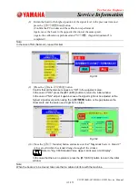
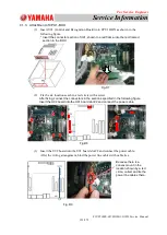
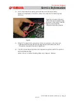
(5) Connect SSD and the power line.
(6)
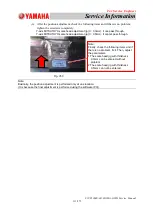
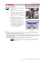
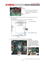
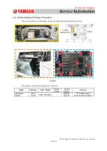
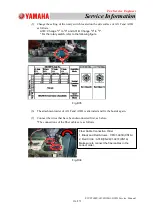
Fix the top cover on the CPU1 BOX and attach the CPU1 BOX specified location in
the machine.
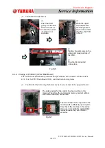
SSD is located on the top
cover of the CPU1 BOX.
Plug the connector in the
section enclosed by a rod
circle.
When it is to be removed,
press the locked section to
unlock and pull it out (Refer
to Fig. D13).
First, attach the set bracket.
* Fix the sections enclosed by red
circle using the four screws
(Refer to Fig. D10). When the
DURACON block is attached,
make sure to press it against the
side surface of U92 and fix
(Refer to Fig. D11).
Four Setscrews
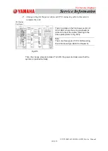
Take care not to step on the
cables when the CPU1 BOX is
returned (Refer to the following
figure).
After it is returned, fix it in the
two locations at the front using
the screws (Refer to the right
figure).
Fig.D10
Fig.D11
Fig.D12
Fig.D13
Fig.D14

