For Service Engineer
Service Information
SI1705004E-00=SIGMA-G5SII Service Manual
151/273
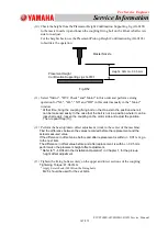
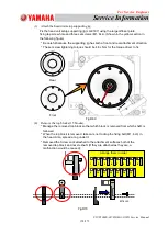
(4) Press the half section of the coupling against the
up/down shaft.
The coupling has both upper and lower directions, so
confirm the direction.
Upper Side (Slip Ring Side) :
8
Lower Side (Center Shaft Side) :
9
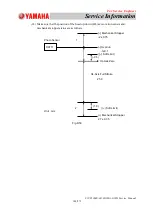
(5) Attach the other section of the coupling and tighten the
four set screws (M3 × L10) for the coupling
temporarily.
①
Adhere the spacer with a thickness of 1mm on the
half section of the divided coupling.
Degrease the adhering surface and adhere it with
Cemedine Super X (No. 8008) and dry. (Refer to
the right figure)
In the case that it has already been adhered, omit
this work.
②
Apply Screw Lock slightly to the set screws (M3 ×
L10) and tighten them.
*Take care not to drop any set screw.
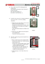
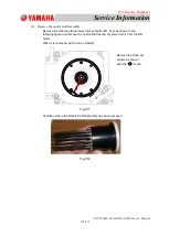
(6) Adjust the coupling fixing position and tighten the set
screws securely.
①
Make sure that the gap in the coupling separated
section should be about "1mm" and the lower gap
should be about "1mm".
*The gap at the coupling separated section should
be "1mm" at both the upper and lower sections
and they should be set in parallel.
*Tightening the set screw after adjusting the one
side (spacer adhesion side) to about 1mm,
facilitates the adjusting operation.
②
Tightening Torque : 10 to 13 cNm (10.8 to 13.2
kgf
cm)
About 1 mm
Fig.D58
Fig.D59
Fig.D60
8
About 1 mm
9


