For Service Engineer
Service Information
SI1705004E-00=SIGMA-G5SII Service Manual
126/273
4.2. Control Board Change
4.2.1. CPU-2 PCBs U85 and U82 Change
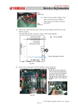
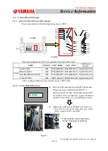
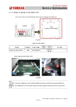
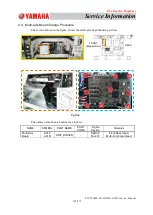
The section shown in the following figure shows CPU-2.
Fig.D16
The Control Boards for CPU-2 are called as follows from the right.
NAME
SYMBOL PART NAME
PART CODE
Fig.No and
Key.No
CPU2
Control CPU
U81
PCB_MOUNT KYB-M410P-10 FigD2-2,No.102
Motion Control
U82
PCB_MOUNT KYB-M4110-00 FigD2-2,No.103
AE-LINK/HSIO Host PCB
U85
PCB_MOUNT KYA-M8625-00 FigD2-2,No.104
Compact Flash
D81
UNIT_I/O(CF) KYB-M410C-00 FigD2-2,No.105
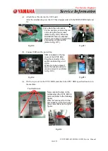
* D81 (Compact Flash) has been attached to the CPU2 board.
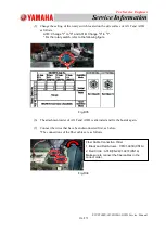
4.2.2. Control Board Removal
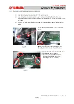
Fig.D17
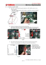
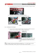
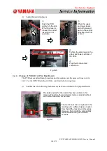
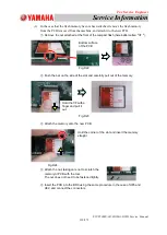
(2) Unplug the connector of the PCB to be removed.
* Take care not to deform the cables (fiber optic cables)
for the connector X8201 and X8202.
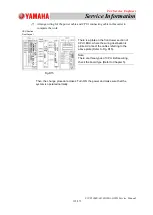
(1) Shut down the machine and turn OFF the breaker.
When a message "NO SIGNAL INPUT" is
displayed in the window, the breaker turning OFF
is available. (Five seconds later, a power shutdown
sound is heard. However, you don't have to wait).
This connector can be removed by
means of pressing its right side.
X9102
X9202
X8500
X8501
X8502
X85UP
X85DN
X85T
X8109
X8104
X8202
X8201
X8102
U85 U82 U81
X8204
X9201
X8203
U92
U91
X9106
X9105
X9109
X9104
X9103
X9108
X9107
FRONT
NO SIGNAL
INPUT


