For Service Engineer
Service Information
SI1705004E-00=SIGMA-G5SII Service Manual
146/273
(7) Adjust the HL-axis height temporarily and assemble the coupling sections on the
motor side and ball screw side.
Adjust the HL-axis height to the position measured before the motor removal and
center the motor side and ball screw side. Then, attach the motor.
* Make sure that the shaft on the ball screw side can be inserted into the motor
without any load, and fix the coupling (on the motor side) temporarily.
(8)
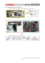
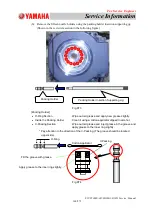
Set the "Placement Height Confirmation Supporting Jig (JG-0191)" around the center
of the backup base and attach the master nozzle to the nozzle No. 1 position in the
head in question.
* Refer to "2.4. Conveyor Width Adjusting Procedure " in Chapter 2, for the setup
procedure for the placement height confirmation supporting jig.
* Setup the jig only on the Z-clamp.
* In the case that the conveyor width clearance is not the same as the set value,
record the value before the change and return it after the work.
* When the NL-axis has not been zeroed, arrange the position where the cam
follower for the nozzle No. 1 is not on the roller rest.
(9)
The X/Y-axis servo motor is turned OFF in the "DVC Check" window and move the
head to the placement section.
Select
"
Maintenance
"
,
"
Engineer
"
,
"
DVC Check
"
and
"
Motor
"
in this order and select
the subject head in the
"
Motor
"
window. Then, select
"
X
"
and click
"
Serve OFF
"
, and
then, select
"
Y1
"
and click
"
Servo OFF
"
.
* The above serial operation is completed; turn ON the servo-motor.
Fig.D51

