For Service Engineer
Service Information
SI1705004E-00=SIGMA-G5SII Service Manual
125/273
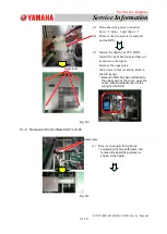
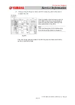
(7) Arrange wiring for the power cable and CPU1 connecting cable in this order to
complete the work.
Then, the change procedure closes. Turn ON the power and make sure that the
system is operated normally.
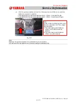
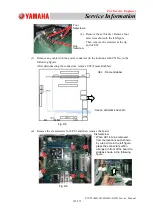
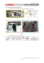
There is a plate on the front lower section of
CPU1 BOX, where the wiring destination is
printed. Connect the cables referring to the
above plate (Refer to Fig. D15).
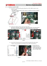
Note:
There are three types of CPU. Before wiring,
check the board type (Refer to Chapter 5).
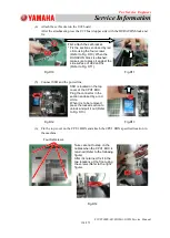
Fig.D15
CPU Section
Front Layout

