For Service Engineer
Service Information
SI1705004E-00=SIGMA-G5SII Service Manual
170/273
4.13. Head Assembly Attachment
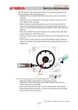
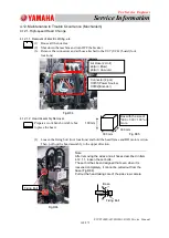
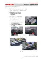
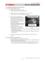
Insert the replacement head from the front side along
the guide. Push it in lightly until it touches the pilot
pin and head fixing guide, taking care of the
inclination on the right and left sides.
Note:
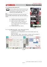
When the head stay is slid along the guide on the both sides,
insert it carefully so that the stay or the x-axis motor cable is not
caught.
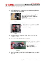
(1) Tighten the head fixing bolt (four locations).
(2) Connect the wires and pipes as before.
(3) Make sure that the wiring or piping does not
interfere with the robot cable or any other
section when the head is moved throughout the
entire movable range.
(4) Turn ON the power to the machine.
4.13.1. SVC Offset Value Input (SVC = Side View Camera)
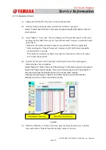
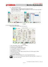
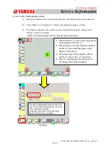
(1) SVC Magnification Offset Value Input
Enter the X [
°
]. Y [
°
], Z [
°
], Magnification X and Y [0.01µm/pixel] values for the
replaced new head.
Select "Sys. Setting", "Offset", "Device Offset", "Line Meas" and "Second Page" in
this order and enter the offset values for the subject head boxes.
Fig.D88
Fig.D87
Guide
Positioning pin
Fixing Guide

