For Service Engineer
Service Information
SI1705004E-00=SIGMA-G5SII Service Manual
180/273
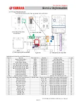
4.17. Fuse Replacement
This section describes the fuse replacement in each block.
Applications for Each Fuse and Standards, etc.
Symbol
Remarks
Downstream Line
Standards
Arranged Location
Location
F2
Safety Circuit (Relay)
24A2
250V, 6.3A
Side Panel Rear
(2)
F5
IO OutPut Power
24A3
250V, 6.3A
U27(UC34)Relay PCB
(1)
F7
Control Power Supply
24A6
250V, 6.3A
Side Panel Rear
(2)
F13
A31 (Head) Main Power (BL1)
48D3A
250V, 6.3A
U27(UC34)Relay PCB
(1)
F14
A31 (Head) Main Power (BL2)
48D3B
250V, 6.3A
U27(UC34)Relay PCB
(1)
F15
A63 (Cutter) Main Power (BL1)
48D3C
250V, 6.3A
U27(UC34)Relay PCB
(1)
F16
A63 (Cutter) Main Power (BL2)
48D3C
250V, 6.3A
U27(UC34)Relay PCB
(1)
F21
Feeder Power (BL1)
24G1A
250V, 6.3A
U27(UC34)Relay PCB
(1)
F23
Feeder Power (BL1)
24G1B
250V, 6.3A
U27(UC34)Relay PCB
(1)
F25
Feeder Power (BL2)
24G2A
250V, 6.3A
U27(UC34)Relay PCB
(1)
F27
Feeder Power (BL2)
24G2B
250V, 6.3A
U27(UC34)Relay PCB
(1)
F200
Lightning Surge Protector
AC200
Outside of the Side Panel Front
(3)
F1
48V Power (CN1)
250V, 10A
U95(UC19) Lighting Control Board
(4)
F2
48V Power (CN1)
250V, 10A
U95(UC19) Lighting Control Board
(4)
F3
24V Power (CON9)
125V, 1A
U95(UC19) Lighting Control Board
(4)
F4
48V Power (CN1)
250V, 10A
U95(UC19) Lighting Control Board
(4)
F5
48V Power (CN1)
250V, 10A
U95(UC19) Lighting Control Board
(4)
F1
PCI Bus_+5V
48V, 2A
CPU2 U85(UC16)I/O Host PCB
(5)
F2
PCI Bus_+3.3V
48V, 2A
CPU2 U85(UC16)I/O Host PCB
(5)
F3
PCI Bus_VIO3.3V
48V, 2A
CPU2 U85(UC16)I/O Host PCB
(5)
F4
AELINK_CH 1
48V, 2A
CPU2 U85(UC16)I/O Host PCB
(5)
F5
AELINK_CH2
48V, 2A
CPU2 U85(UC16)I/O Host PCB
(5)
F6
24V
48V, 2A
CPU2 U85(UC16)I/O Host PCB
(5)
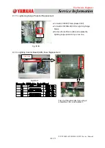
①
②
①
Relay PCB (U27)
③
③
Outside of the Side
Panel Front
④
④
U95 Lighting Control Board
⑤
⑤
CPU2(U85) I/O Host PCB
②
Side Panel Rear
Fig.D105
Fuse in Each board (Because there is no description about it in “Materials” section in Volume 5 in the Instruction Manual, the symbols are allotted temporarily).

