For Service Engineer
Service Information
SI1705004E-00=SIGMA-G5SII Service Manual
185/273
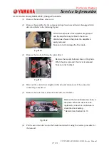
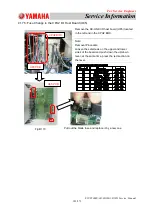
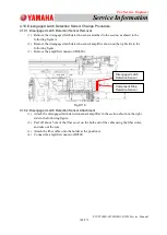
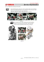
(5) Remove the upper screw fixing the servo-amplifier body and loosen the two lower
、
screws and pull out the servo-amplifier.
* A screwdriver with the bit length of 30cm or more is required.
* For the servo amplifier main body setscrews (2 pcs) in the lower section, because
the mechanism on the main body side is as shown in the left figure, all you have to
do is just loosening them.
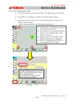
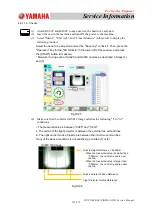
(6) Because the earth cable has been fixed
using a screw under the servo-amplifier
pull the servo-amplifier out to a point
where it can easily be removed.
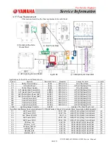
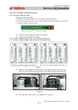
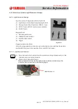
4.18.2. Servo-Amplifier Attachment
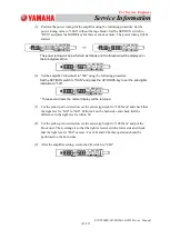
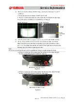
Attach the subject servo amplifier.
Set the values for "SW1" and "SW2" for the
subject amplifier, based on the following table.
AMP
SW1
(address)
SW2
UVW
CN1A
CN1B
CN2
CN2L
CN3
A21F
0
↓
Settng
XM21PF
X211AF
X211BF
X2102F
X2102LF
X2103F
A22F
1
XM22PF
X221AF
X221BF
X2202F
X2202LF
X2203F
A23F
2
XM23PF
X231AF
X2302F
X2302LF
A21B
3
XM21PB
X211AB
X211BB
X2102B
X2102LB
X2103B
A22B
6
XM22PB
X221AB
X221BB
X2202B
X2202LB
X2203B
A23B
7
XM23PB
X231AB A21F-CN1B X2302B
X2302LB
Servo-Amplifier Body
Lower
Section Set Screws
Earth Terminal
SW2
SW2
Fig.D113
Fig.D114
Fig.D115
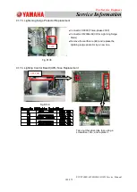
Servo-Amplifier Body
Rear
Side Lower Section

