For Service Engineer
Service Information
SI1705004E-00=SIGMA-G5SII Service Manual
145/273
4.9.1. Head Up/Down (HL) Axis Motor Attachment
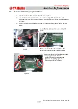
(1) Degrease sufficiently the shaft section of the motor to be attached, with alcohol
(solvent).
(2) Temporarily attach the removed coupling to
the motor shaft. Apply Screw Lock (1401B)
slightly onto the coupling fixing bolt.
* Arrange it so that the gap between the
coupling and motor shaft root section
becomes about 2.5mm.
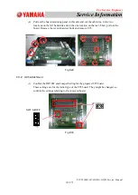
(3) Connect the motor cable connectors and
arrange the wiring.
* In the wire arrangement, take care of the
arrangement so that there is no twist or
bend due to sliding.
(Return to the original condition).
(4) Turn ON the power to the machine and start
it up.
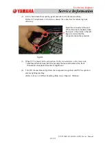
(5) Zero (to view Phase C) the head up/down
(HL Axis) motor manually at the position
where there is no obstacle (such as nozzle
stocker) under the head.
①
Shade the upper photo sensor (X0711).
②
Select "Maint.", "DVC Check" and
"Motor" in this order and select the
changed block.
Then, select "HL" and "Selection Axis"
in this order, and press the [START]
button in the "Selection Axis" window.
③
Remove the shade from the photo sensor
immediately after the motor starts
moving.
④
Wait until the motor is stopped.
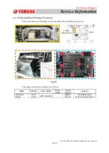
(6) Tighten the coupling temporarily in the position where the set bolt can be tightened
when the motor is in the home position and the motor is attached (Refer to Item 6.1.
(2)).
2.5mm
Fig.D50
Fig.D49
Photo Sensor
(X0711)

