


Chapter 10 PCI Controller
10-14
PCI Reset is detected by either using the PCI Bus Reset Signal as the TX4937 overall reset signal or
using the PCI Bus Reset Signal assertion detection device that the system provides. Then, the software
reset the PCI Controller. The software uses a hardware reset (PCICCFG.HRST) of the PCI Controller
Configuration Register to reset the PCI Controller.
10.3.9 Power
Management
The TX4937 PCI Controller supports power management functions that are compliant to PCI Bus
Power Management Interface Specifications Version 1.1.
The PCI Host device controls the system status by reporting the power management state to the PCI
Satellite device. Also, the PCI Satellite device uses the PME* signal to report requests for changing the
power management state or to report to the PCI Host device that a power management event has
occurred.
10.3.9.1 Power
Management
State
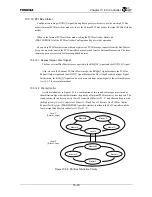
In the case of the PCI Bus Power Management Interface Specifications, four power
management states are defined from State D0 to State D3. The TX4937 supports states D0 through
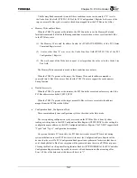
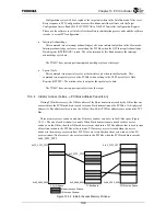
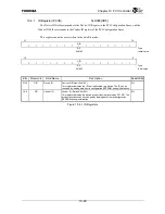
D3. Figure 10.3.7 illustrates the power management state transition.
After Power On Reset, or when transitioning from the D3
HOT
state to the D0 state, the power
management state becomes uninitialized D0. If initialized by the system software at this point, the
state transitions to D0 Active.
If an external PCI Host device writes 11b (D3
HOT
) to the PowerState field of the Power
Management Control Status Register (PMCSR) of the Configuration space when in the Satellite
mode, then the Power Management State Change bit (P2GSTATUS.PMSC) of the P2G Status
Register is set and transitions to the D3
HOT
state. It then becomes possible to report Power State
Change interrupts. The PowerState field value can be read from the PowerState field
(PCISSTATUS.PS) of the Satellite Mode PCI Status Register.
The TX4937 uses the software to change the system status after a status change is detected.
Figure 10.3.7 Transition of the Power Management States
D0
Uninitialized
D0 Active
D3
hot
D3
cold
PCI RST
*
*
(RESET
*
*
)
VCCCut-off
Software Reset
Power On Reset
(RESET
*
*
)
Initialization by the
System Software
Change PMCSR
PowerState
Содержание TX49 TMPR4937
Страница 1: ...64 Bit TX System RISC TX49 Family TMPR4937 Rev 2 0 ...
Страница 4: ......
Страница 13: ...Table of Contents ix TMPR4937 Revision History 1 ...
Страница 14: ...Table of Contents x ...
Страница 15: ...Handling Precautions ...
Страница 16: ......
Страница 18: ...1 Using Toshiba Semiconductors Safely 1 2 ...
Страница 40: ...3 General Safety Precautions and Usage Considerations 3 18 ...
Страница 42: ...4 Precautions and Usage Considerations 4 2 ...
Страница 43: ...TMPR4937 2005 3 Rev 2 0 ...
Страница 44: ......
Страница 52: ...Chapter 1 Overview and Features 1 6 ...
Страница 156: ...Chapter 7 External Bus Controller 7 56 ...
Страница 491: ...Chapter 16 Removed 16 1 16 Removed ...
Страница 492: ...Chapter 16 Removed 16 2 ...
Страница 493: ...Chapter 17 Removed 17 1 17 Removed ...
Страница 494: ...Chapter 17 Removed 17 2 ...
Страница 495: ...Chapter 18 Removed 18 1 18 Removed ...
Страница 496: ...Chapter 18 Removed 18 2 ...
Страница 497: ...Chapter 19 Removed 19 1 19 Removed ...
Страница 498: ...Chapter 19 Removed 19 2 ...
Страница 506: ...Chapter 20 Extended EJTAG Interface 20 8 ...
Страница 529: ...Chapter 22 Pinout and Package Information 22 9 22 2 Package Dimensions P BGA484 3535 1 27B9 Unit mm ...
Страница 530: ...Chapter 22 Pinout and Package Information 22 10 ...
Страница 542: ...Chapter 24 Parts Number when Ordering 24 2 ...
Страница 544: ...Appendix A TX49 H3 Core Supplement A 2 ...


