


Chapter 8 DMA Controller
8-31
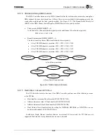
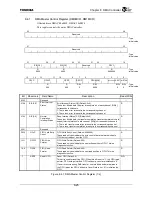
8.4.3
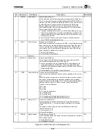
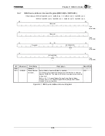
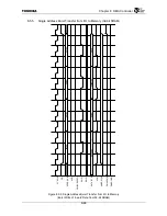
DMA Channel Status Register (DM0CSRn, DM1CSRn))
Offset Address: DMAC0 0xB038 (ch. 0) / 0xB078 (ch. 1) / 0xB0B8 (ch. 2) / 0xB0F8 (ch. 3)
DMAC1 0xB838 (ch. 0) / 0xB878 (ch. 1) / 0xB8B8 (ch. 2) / 0xB8F8 (ch. 3)
63
48
Reserved
: Type
: Initial value
47
32
Reserved
: Type
: Initial value
31
16
WAITC
R
: Type
0x0000
: Initial value
15
11 10 9 8 7 6 5 4 3 2 1 0
Reserved
CHNEN
STLXFER
XFACT ABCHC NCHNC
NTRNFC
EXTDN CFERR CHERR
DESERR SORERR
R
R/W1C
R
R
R/W1C R/W1C R/W1C R/W1C R/W1C R/W1C R/W1C : Type
0 0 0 0 0 0 0 0 0 0 0
: Initial value
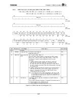
Bit Mnemonic Field
Name
Description Read/Write
63:32 Reserved
⎯
31:16
WAITC
Wait Counter
Wait Counter (Default: 0x0000)
This is a diagnostic function.
•
I/O DMA transfer mode (DMCCRn.EXTRQ = “1”)
This counter is decremented by 1 at each 64 G-Bus cycles. After channel
n
releases bus ownership, this counter sets the default (the value that is the
detection interval clock cycle count set by the Transfer Stall Detection
Interval field (DMCCRn.STLTIME) divided by 64). The Transfer Stall
Detect bit (DMCSRn.STLXFER) is set when the interval during which bus
ownership is not held reaches the set clock cycle. The counter is reset to
the default and stops counting. Clearing the Transfer Stall Detect bit
(DMCSRn.STLXFER) resumes the count and starts stall detection.
•
Memory transfer mode (DMCCRn.EXTRQ = “0”)
This counter is decremented by 1 at each G-Bus cycle. After bus
ownership is released, the counter is set to the delay clock cycle count set
by the Internal Request Delay field (DMCCRn.INTRQD). When the counter
reaches “0” the count stops and channel
n
requests bus ownership.
R
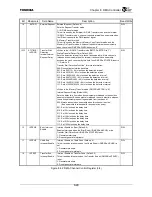
15:11 Reserved
⎯
10
CHNEN
Chain Enable
Chain Enable (Default: 0)
This value is a copy of the Chain Enable bit (CHNEN) of the DMA Channel
Control Register (DMCCRn).
R
9 STLXFER
Transfer Stall
Detect
Stalled Transfer Detect (Default: 0)
This bit indicates whether the interval during which bus ownership is not
held exceeds the value set by the Transfer Stall Detect Interval field
(DMCCRn.STLTIME) after bus ownership is released when in the I/O DMA
transfer mode.
1: Indicates that the interval during which bus ownership was not held
exceeds the DMCCRn.STLTIME setting.
0: The interval during which bus ownership was not held did not exceed
the setting since this bit was last cleared.
R/W1C
Figure 8.4.3 DMA Channel Status Register (1/2)
Содержание TX49 TMPR4937
Страница 1: ...64 Bit TX System RISC TX49 Family TMPR4937 Rev 2 0 ...
Страница 4: ......
Страница 13: ...Table of Contents ix TMPR4937 Revision History 1 ...
Страница 14: ...Table of Contents x ...
Страница 15: ...Handling Precautions ...
Страница 16: ......
Страница 18: ...1 Using Toshiba Semiconductors Safely 1 2 ...
Страница 40: ...3 General Safety Precautions and Usage Considerations 3 18 ...
Страница 42: ...4 Precautions and Usage Considerations 4 2 ...
Страница 43: ...TMPR4937 2005 3 Rev 2 0 ...
Страница 44: ......
Страница 52: ...Chapter 1 Overview and Features 1 6 ...
Страница 156: ...Chapter 7 External Bus Controller 7 56 ...
Страница 491: ...Chapter 16 Removed 16 1 16 Removed ...
Страница 492: ...Chapter 16 Removed 16 2 ...
Страница 493: ...Chapter 17 Removed 17 1 17 Removed ...
Страница 494: ...Chapter 17 Removed 17 2 ...
Страница 495: ...Chapter 18 Removed 18 1 18 Removed ...
Страница 496: ...Chapter 18 Removed 18 2 ...
Страница 497: ...Chapter 19 Removed 19 1 19 Removed ...
Страница 498: ...Chapter 19 Removed 19 2 ...
Страница 506: ...Chapter 20 Extended EJTAG Interface 20 8 ...
Страница 529: ...Chapter 22 Pinout and Package Information 22 9 22 2 Package Dimensions P BGA484 3535 1 27B9 Unit mm ...
Страница 530: ...Chapter 22 Pinout and Package Information 22 10 ...
Страница 542: ...Chapter 24 Parts Number when Ordering 24 2 ...
Страница 544: ...Appendix A TX49 H3 Core Supplement A 2 ...