1 - 10
1. FUNCTIONS AND CONFIGURATION
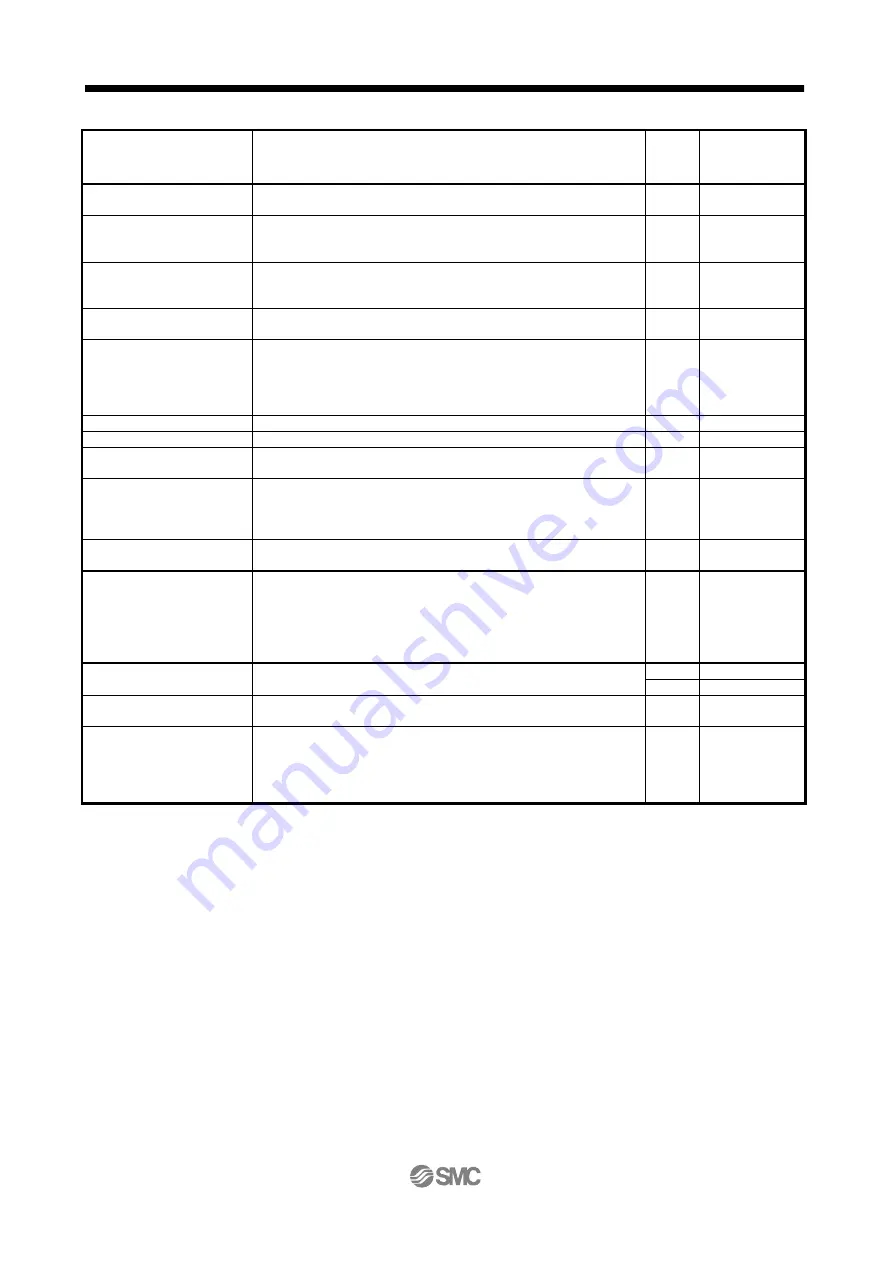
Function
Description
(Note)
Control
mode
Reference
Command pulse selection
Command input pulse form can be selected from among three different
types.
P
Section 4.1.11
Input signal selection
Forward rotation start, reverse rotation start, servo-on (SON) and other
input device can be assigned to specific pins.
P, S, T
Parameter
No. PD03 to
PD14
Output signal selection
Ready (RD), trouble (ALM) or other output device can be assigned to
specific pins.
P, S, T
Parameter
No. PD15 to
PD18
Torque limit
The torque generated by the servo motor can be limited by setting a
parameter.
P, S
Section 3.6.1 (4)
Section 4.1.10
Speed limit
Servo motor speed can be limited by setting a parameter.
T
Section 3.6.3 (3)
Parameter
No. PC05 to
PC08, PC31 to
PC34
Status display
Servo status is shown on the 3-digit, 7-segment LED display
P, S, T Section 5.3
External I/O signal display
ON/OFF statuses of external I/O signals are shown on the display.
P, S, T Section 5.7
Output signal (DO)
forced output
Output signal can be forced on/off independently of the servo status.
Use this function for output signal wiring check, etc.
P, S, T Section 5.8
Test operation mode
JOG operation, positioning operation, motor-less operation, DO forced
output, and forced tough drive operation.
However, set up software(MR Configurator2
TM
) is necessary for the
positioning operation.
P, S, T Section 5.9
Software
(MR Configurator2
TM
)
Parameter setting, test operation, status display, etc. can be performed
using a personal computer.
P, S, T Section 11.4
Tough drive function
This function continues the operation not to stop a machine in such
situation when normally an alarm is activated.
Three types of the tough drive function are available: overload tough
drive, vibration tough drive and instantaneous power failure tough drive.
However, the overload tough drive is valid only in the position control
mode.
P, S
Section 7.1
Limit switch
The servo motor travel region can be limited using the forward rotation
stroke end (LSP)/reverse rotation stroke end (LSN).
P, S
Section 3.5
CP/CL Section 13.2.3
Software limit (Note2)
The travel region is limited using parameters in terms of address.
The function similar to that of a limit switch is limited by parameter.
CP/CL Section 13.7.5 (4)
Drive recorder function
(Note2)
This function records the state transition before and after the alarm
occurrence for the predetermined period of time by always monitoring
the servo status. The recorded data can be confirmed on the graph
display screen by clicking the "Drive recorder display" button on the
alarm history display screen of MR Configurator2
TM
.
P, S, T
CP/CL
Section 4.3.4
Note 1. P: Position control mode, S: Internal speed control mode, T: Internal torque control mode,
P/S: Position/internal speed control change mode, S/T: Internal speed/internal torque control change mode,
T/P: Internal torque/position control change mode
CP: Positioning mode (Point table method), CL: Positioning mode (Program method)
2. It is supported by driver with software version B0 or later.


