13 - 84
13. POSITIONING MODE
(2) List of details
No.
Symbol
Name and function
Initial
value
Setting
range
Unit
PE01
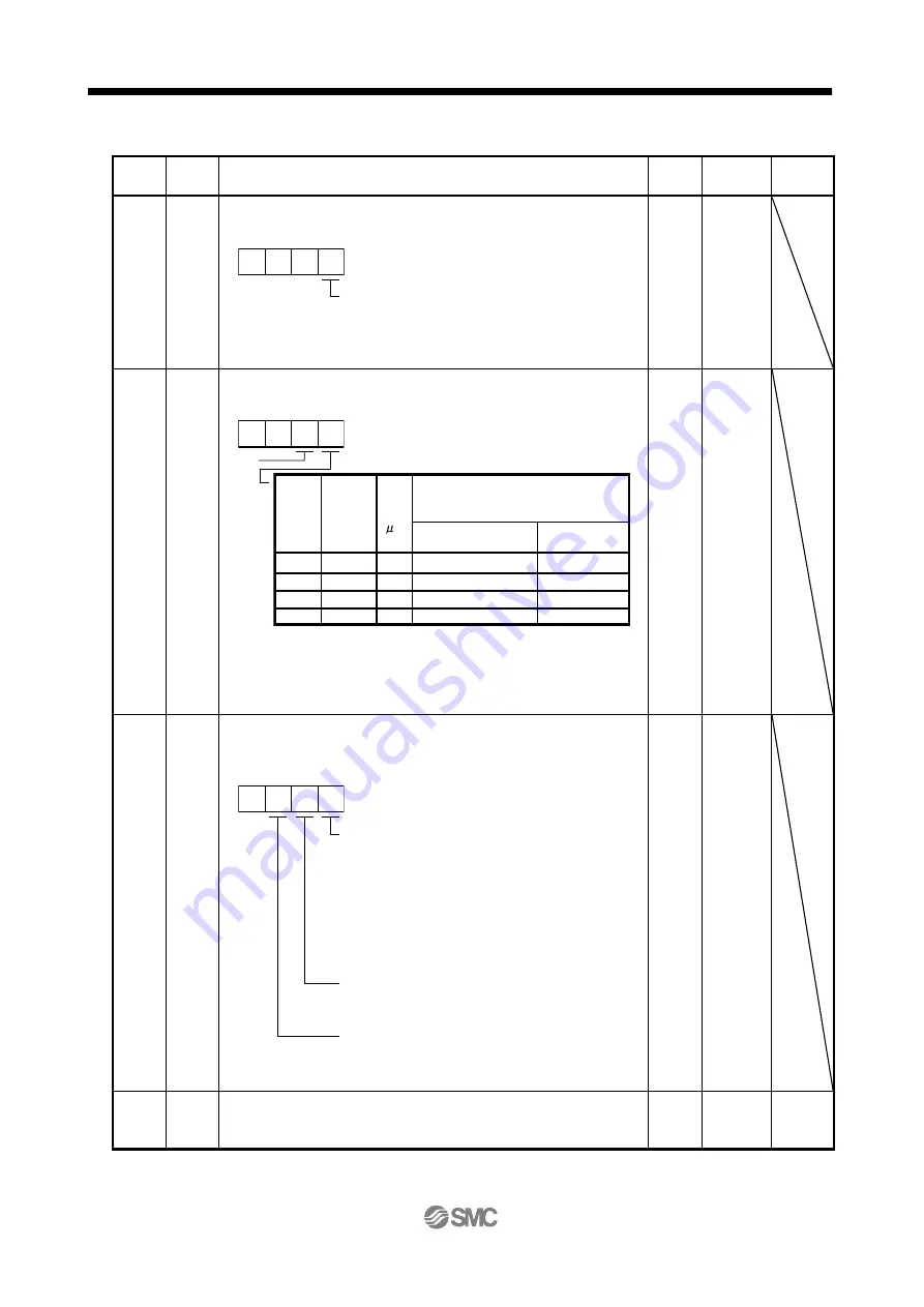
*CTY
Command mode selection
Select the command system.
Selection of command system
(Refer to section 13.3 and 13.4)
0: Absolute value command system
1: Incremental value command system
0 0 0
0000h Refer to
the name
and
function
filed.
PE02
*FTY
Feeding function selection
Select the feed length multiplication.
0 0
Manual pulse generator multiplication
0: 1 time
1: 10 times
2: 100 times
Set
value
1
2
3
0
Feed
length
multipli-
cation
(ST M)
[Multiplier]
Feed
unit
[ m]
-999.999 to +999.999
0 to +999.999
Absolute value
command system
Incremental value
command system
Position data input range [mm]
1
1
10
100
100
1000
1000
-9999.99 to +9999.99
0 to +9999.99
-99999.9 to +99999.9
0 to +99999.9
-999999 to +999999
0 to +999999
10
0000h Refer to
the name
and
function
filed.
PE03
*ZTY
Home position return type
Select the home position return type, home position return direction and
proximity dog input polarity. (Refer to section 13.6.)
Home position return type
0: Dog type
1: Count type
2: Data set type
3: Stopper type
4: Home position ignorance
(Servo-on position as home position)
5: Dog type rear end reference
6: Count type front end reference
7: Dog cradle type
0
Home position return direction
0: Address increasing direction
1: Address decreasing direction
Proximity dog input polarity
0: OFF indicates detection of the dog
1: ON indicates detection of the dog
0010h Refer to
the name
and
function
filed.
PE04
ZRF
Home position return speed
Used to set the servo motor speed for home position return. (Refer to
section 13.6.)
500
0 to
permissible
speed
r/min


