


2 Functions
74
7UT613/63x Manual
C53000-G1176-C160-2
Current Transform-
er Data for Single-
phase Busbar Pro-
tection
The operational nominal currents of each feeder have already been set under margin
heading „Object Data with Busbars (1-phase Connection) with up to 9 or 12 Feeders“.
The feeder currents are referred to these nominal feeder currents. However, the rated
currents of the current transformers may differ from the nominal feeder currents.
Therefore, the device must be informed about the current transformer data, too. In
figure
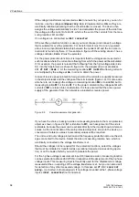
2-15 the rated CT currents are 1000 A (feeder 1), 500 A (feeder 2 and 3).
If rated currents have already been matched by external equipment (e.g. by matching
transformers), the rated current value, used as a base value for the calculation of the
external matching transformers, is to be indicated uniform. Normally, it is the rated op-
erational current. The same applies if external summation transformers are used.
Indicate the rated primary transformer current for each feeder. The interrogation only
applies to data of the number of feeders determined during the configuration accord-
ing to section 2.1.4, margin heading „Global Data for 1-phase Busbar Protection“ (ad-
dress
216
NUMBER OF ENDS
).
For rated secondary currents please make sure that rated secondary transformer cur-
rents match with the rated current of the corresponding current input of the device.
Rated secondary currents of a device can be matched. If summation transformers are
used, the rated current at the outgoing side is usually 100 mA. For rated secondary
currents a value of
0.1
A is therefore set for all feeders.
Indication of the starpoint position of the current transformers determines the polarity
of the current transformers. Set for each feeder if the starpoint is looking towards the
busbar or not. Figure 2-15 shows an example of 3 feeders in which the transformer
starpoint in feeder 1 and feeder 3 are looking towards the busbar, unlike feeder 2.
If external interposed transformers are used, it is presumed that these are connected
with correct polarity.
Figure 2-15
Position of the CT starpoints — example for phase L1 of a busbar with 3 feeders
Hereinafter the parameters for the individual feeders:
Содержание SIPROTEC 7UT613 series
Страница 16: ...Contents 16 7UT613 63x Manual C53000 G1176 C160 2 Literature 631 Glossary 623 Index 633 ...
Страница 30: ...1 Introduction 30 7UT613 63x Manual C53000 G1176 C160 2 ...
Страница 506: ...A Appendix 506 7UT613 63x Manual C53000 G1176 C160 2 7UT633 D E ...
Страница 508: ...A Appendix 508 7UT613 63x Manual C53000 G1176 C160 2 7UT633 P Q ...
Страница 510: ...A Appendix 510 7UT613 63x Manual C53000 G1176 C160 2 7UT635 D E ...
Страница 512: ...A Appendix 512 7UT613 63x Manual C53000 G1176 C160 2 7UT635 P Q ...
Страница 515: ...A 2 Terminal Assignments 515 7UT613 63x Manual C53000 G1176 C160 2 7UT633 B ...
Страница 516: ...A Appendix 516 7UT613 63x Manual C53000 G1176 C160 2 7UT633 B Figure A 7 General diagram 7UT633 panel surface mounting ...
Страница 517: ...A 2 Terminal Assignments 517 7UT613 63x Manual C53000 G1176 C160 2 7UT633 N ...
Страница 518: ...A Appendix 518 7UT613 63x Manual C53000 G1176 C160 2 7UT633 N Figure A 8 General diagram 7UT633 panel surface mounting ...
Страница 519: ...A 2 Terminal Assignments 519 7UT613 63x Manual C53000 G1176 C160 2 7UT635 B ...
Страница 520: ...A Appendix 520 7UT613 63x Manual C53000 G1176 C160 2 7UT635 B Figure A 9 General diagram 7UT635 panel surface mounting ...
Страница 521: ...A 2 Terminal Assignments 521 7UT613 63x Manual C53000 G1176 C160 2 7UT635 N ...
Страница 522: ...A Appendix 522 7UT613 63x Manual C53000 G1176 C160 2 7UT635 N Figure A 10 General diagram 7UT635 panel surface mounting ...
Страница 622: ...A Appendix 622 7UT613 63x Manual C53000 G1176 C160 2 ...
Страница 632: ...Literature 632 7UT613 63x Manual C53000 G1176 C160 2 ...


