


2 Functions
142
7UT613/63x Manual
C53000-G1176-C160-2
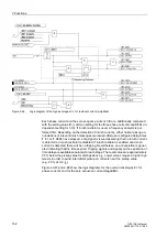
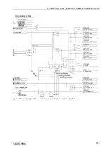
Figure 2-57
Example for an earth fault in a transformer with current distribution
When an earth fault occurs outside the protected zone (Figure 2-58), a starpoint
current
I
Ctrl
will flow equally; but an equal current 3
I
0
must flow through the phase
current transformers. Since the current direction is normally defined as positive in the
direction of the protected object, this current is in phase opposition with
I
Ctrl
.
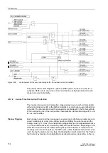
Figure 2-58
Example for an earth fault outside a transformer with current distribution
When a fault without earth connection occurs outside the protected zone, a residual
current may occur in the residual current path of the phase current transformers which
is caused by different saturation of the phase current transformers under strong
through-current conditions. This current could simulate a fault in the protected zone.
Measures must be taken to prevent this current from causing a trip. For this, the re-
stricted earth fault protection provides stabilisation methods which differ strongly from
the usual stabilisation methods of differential protection schemes since it uses,
besides the magnitude of the measured currents, the phase relationship, too.
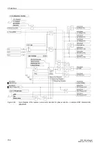
Evaluation of Mea-
surement Quanti-
ties
The earth fault differential protection compares the fundamental wave of the current
flowing in the starpoint connection, which is designated as 3
I
0
' in the following, with
the fundamental wave of the sum of the phase currents, which should be designated
in the following as 3
I
0
". Thus, the following applies (Figure 2-59):
3
I
0
' =
I
Ctrl
3
I
0
" =
I
L1
+
I
L2
+
I
L3
Only 3
I
0
' acts as the tripping effect quantity. During a fault within the protected zone
this current is always present.
Содержание SIPROTEC 7UT613 series
Страница 16: ...Contents 16 7UT613 63x Manual C53000 G1176 C160 2 Literature 631 Glossary 623 Index 633 ...
Страница 30: ...1 Introduction 30 7UT613 63x Manual C53000 G1176 C160 2 ...
Страница 506: ...A Appendix 506 7UT613 63x Manual C53000 G1176 C160 2 7UT633 D E ...
Страница 508: ...A Appendix 508 7UT613 63x Manual C53000 G1176 C160 2 7UT633 P Q ...
Страница 510: ...A Appendix 510 7UT613 63x Manual C53000 G1176 C160 2 7UT635 D E ...
Страница 512: ...A Appendix 512 7UT613 63x Manual C53000 G1176 C160 2 7UT635 P Q ...
Страница 515: ...A 2 Terminal Assignments 515 7UT613 63x Manual C53000 G1176 C160 2 7UT633 B ...
Страница 516: ...A Appendix 516 7UT613 63x Manual C53000 G1176 C160 2 7UT633 B Figure A 7 General diagram 7UT633 panel surface mounting ...
Страница 517: ...A 2 Terminal Assignments 517 7UT613 63x Manual C53000 G1176 C160 2 7UT633 N ...
Страница 518: ...A Appendix 518 7UT613 63x Manual C53000 G1176 C160 2 7UT633 N Figure A 8 General diagram 7UT633 panel surface mounting ...
Страница 519: ...A 2 Terminal Assignments 519 7UT613 63x Manual C53000 G1176 C160 2 7UT635 B ...
Страница 520: ...A Appendix 520 7UT613 63x Manual C53000 G1176 C160 2 7UT635 B Figure A 9 General diagram 7UT635 panel surface mounting ...
Страница 521: ...A 2 Terminal Assignments 521 7UT613 63x Manual C53000 G1176 C160 2 7UT635 N ...
Страница 522: ...A Appendix 522 7UT613 63x Manual C53000 G1176 C160 2 7UT635 N Figure A 10 General diagram 7UT635 panel surface mounting ...
Страница 622: ...A Appendix 622 7UT613 63x Manual C53000 G1176 C160 2 ...
Страница 632: ...Literature 632 7UT613 63x Manual C53000 G1176 C160 2 ...


