


2 Functions
54
7UT613/63x Manual
C53000-G1176-C160-2
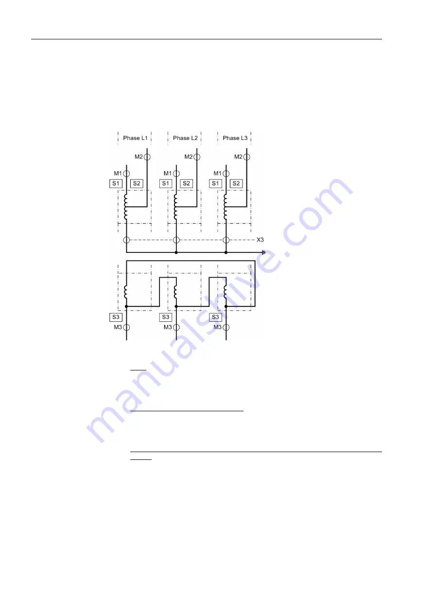
The sum of the three currents measured in the starpoint leads can be connected to an
auxiliary 1-phase current input of the device (illustrated dotted) in order to use it for
restricted earth fault protection and/or time overcurrent protection. This auxiliary mea-
suring location
X3
is then assigned to both sides
S1
and
S2
, since the current entering
the protected object at
X3
must be compared with the sum of the currents at both
sides. More details with regard to the assignment are discussed later.
Figure 2-6
Topology of a transformer bank consisting of 3 single-phase auto-transformers
with compensation winding dimensioned as accessible tertiary winding
Sides:
S1
High voltage side of the auto-connected winding of the main protected object
S2
Low voltage side (tap) of the auto-connected winding of the main protected object
S3
Tertiary winding side (accessible compensation winding) of the main protected object
Measuring locations 3-phase, assigned:
M1
Measuring location, assigned to the main protected object, side 1
M2
Measuring location, assigned to the main protected object, side 2
M3
Measuring location, assigned to the main protected object, side 3
Auxiliary measuring locations, 1-phase, assigned to the main object (current sum of the
CT set):
X3
Measuring location, assigned to the main protected object, side 1 and 2
Содержание SIPROTEC 7UT613 series
Страница 16: ...Contents 16 7UT613 63x Manual C53000 G1176 C160 2 Literature 631 Glossary 623 Index 633 ...
Страница 30: ...1 Introduction 30 7UT613 63x Manual C53000 G1176 C160 2 ...
Страница 506: ...A Appendix 506 7UT613 63x Manual C53000 G1176 C160 2 7UT633 D E ...
Страница 508: ...A Appendix 508 7UT613 63x Manual C53000 G1176 C160 2 7UT633 P Q ...
Страница 510: ...A Appendix 510 7UT613 63x Manual C53000 G1176 C160 2 7UT635 D E ...
Страница 512: ...A Appendix 512 7UT613 63x Manual C53000 G1176 C160 2 7UT635 P Q ...
Страница 515: ...A 2 Terminal Assignments 515 7UT613 63x Manual C53000 G1176 C160 2 7UT633 B ...
Страница 516: ...A Appendix 516 7UT613 63x Manual C53000 G1176 C160 2 7UT633 B Figure A 7 General diagram 7UT633 panel surface mounting ...
Страница 517: ...A 2 Terminal Assignments 517 7UT613 63x Manual C53000 G1176 C160 2 7UT633 N ...
Страница 518: ...A Appendix 518 7UT613 63x Manual C53000 G1176 C160 2 7UT633 N Figure A 8 General diagram 7UT633 panel surface mounting ...
Страница 519: ...A 2 Terminal Assignments 519 7UT613 63x Manual C53000 G1176 C160 2 7UT635 B ...
Страница 520: ...A Appendix 520 7UT613 63x Manual C53000 G1176 C160 2 7UT635 B Figure A 9 General diagram 7UT635 panel surface mounting ...
Страница 521: ...A 2 Terminal Assignments 521 7UT613 63x Manual C53000 G1176 C160 2 7UT635 N ...
Страница 522: ...A Appendix 522 7UT613 63x Manual C53000 G1176 C160 2 7UT635 N Figure A 10 General diagram 7UT635 panel surface mounting ...
Страница 622: ...A Appendix 622 7UT613 63x Manual C53000 G1176 C160 2 ...
Страница 632: ...Literature 632 7UT613 63x Manual C53000 G1176 C160 2 ...


