


2 Functions
274
7UT613/63x Manual
C53000-G1176-C160-2
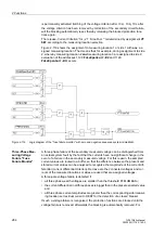
The delay time
T1
(address
7115
) is then set to
∞
since it is not needed.
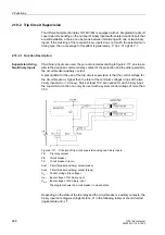
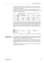
The delay times are determined from the maximum operating time of the feeder circuit
breaker, the reset time of the current detectors of the breaker failure protection, plus
a safety margin which allows for any tolerance of the delay timers. The time sequenc-
es are illustrated in Figure 2-111. For sinusoidal currents one can assume that the
reset time of the current detectors is about
1
/
2
cycle but if current transformer satura-
tion is expected, then1
1
/
2
cycles should be assumed as worst case.
Figure 2-111
Time sequence for normal clearance of a fault, and with circuit breaker failure
example for single-stage breaker failure protection
Additional Circuit
Breaker Failure
Protection Func-
tions
In the aforementioned description, the first circuit breaker failure protection is de-
scribed respectively. The differences in the parameter addresses and message
numbers of the first and second circuit breaker failure protection are illustrated in the
following table. The positions marked by x are identical.
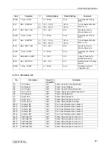
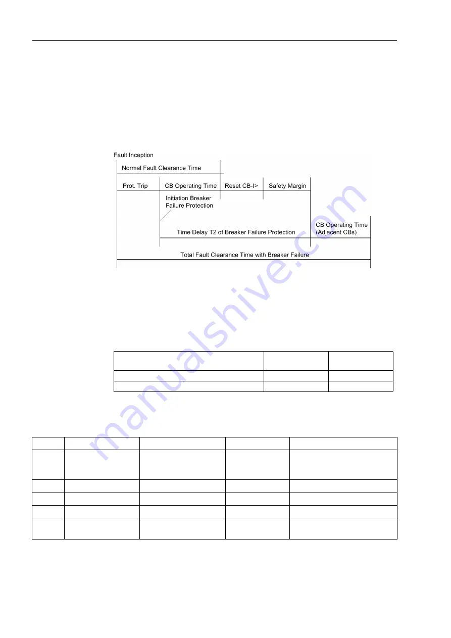
2.17.3 Settings
Parameter address-
es
Message no.
1. Circuit breaker failure protection
70xx
047.xxxx(.01)
2. Circuit breaker failure protection
71xx
206.xxxx(.01)
Addr.
Parameter
Setting Options
Default Setting
Comments
7001
BREAKER FAILURE
OFF
ON
Block relay
OFF
Breaker Failure Protection
7011
START WITH REL.
0 .. 8
0
Start with Relay (intern)
7012
START WITH REL.
0 .. 24
0
Start with Relay (intern)
7015
T1
0.00 .. 60.00 sec;
∞
0.15 sec
T1, Delay of 1st stage (local trip)
7016
T2
0.00 .. 60.00 sec;
∞
0.30 sec
T2, Delay of 2nd stage (busbar
trip)
Содержание SIPROTEC 7UT613 series
Страница 16: ...Contents 16 7UT613 63x Manual C53000 G1176 C160 2 Literature 631 Glossary 623 Index 633 ...
Страница 30: ...1 Introduction 30 7UT613 63x Manual C53000 G1176 C160 2 ...
Страница 506: ...A Appendix 506 7UT613 63x Manual C53000 G1176 C160 2 7UT633 D E ...
Страница 508: ...A Appendix 508 7UT613 63x Manual C53000 G1176 C160 2 7UT633 P Q ...
Страница 510: ...A Appendix 510 7UT613 63x Manual C53000 G1176 C160 2 7UT635 D E ...
Страница 512: ...A Appendix 512 7UT613 63x Manual C53000 G1176 C160 2 7UT635 P Q ...
Страница 515: ...A 2 Terminal Assignments 515 7UT613 63x Manual C53000 G1176 C160 2 7UT633 B ...
Страница 516: ...A Appendix 516 7UT613 63x Manual C53000 G1176 C160 2 7UT633 B Figure A 7 General diagram 7UT633 panel surface mounting ...
Страница 517: ...A 2 Terminal Assignments 517 7UT613 63x Manual C53000 G1176 C160 2 7UT633 N ...
Страница 518: ...A Appendix 518 7UT613 63x Manual C53000 G1176 C160 2 7UT633 N Figure A 8 General diagram 7UT633 panel surface mounting ...
Страница 519: ...A 2 Terminal Assignments 519 7UT613 63x Manual C53000 G1176 C160 2 7UT635 B ...
Страница 520: ...A Appendix 520 7UT613 63x Manual C53000 G1176 C160 2 7UT635 B Figure A 9 General diagram 7UT635 panel surface mounting ...
Страница 521: ...A 2 Terminal Assignments 521 7UT613 63x Manual C53000 G1176 C160 2 7UT635 N ...
Страница 522: ...A Appendix 522 7UT613 63x Manual C53000 G1176 C160 2 7UT635 N Figure A 10 General diagram 7UT635 panel surface mounting ...
Страница 622: ...A Appendix 622 7UT613 63x Manual C53000 G1176 C160 2 ...
Страница 632: ...Literature 632 7UT613 63x Manual C53000 G1176 C160 2 ...


