


2.1 General
63
7UT613/63x Manual
C53000-G1176-C160-2
forward power monitoring, the frequency protection, or for measuring tasks like the
display of voltages or the calculation and output of power and energy metering.
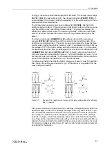
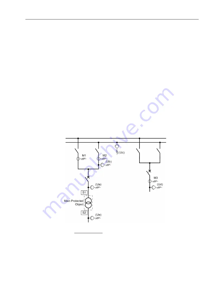
Figure 2-8 shows the various possible voltage assignments (which, of course do not
occur all at the same time in practice). Address
261
must be set to
VT SET
.
• For voltage measurement at
Ua
the voltages are measured on
Side 1
of the main
protected object.
• For voltage measurement at
Ub
, the voltages at the
Measuring loc.2
are mea-
sured that are assigned to side 1 of the main protected object.
• For voltage measurement at
Uc
the voltages are measured at the
Busbar
(only
possible in busbar protection).
• For voltage measurement at
Ud
, voltages at the
Measuring loc.3
are measured
that are not assigned to the main protected object.
• For voltage measurement at
Ue
the voltages are measured on
Side 2
of the main
protected object.
As these examples show, you can select sides, busbars, assigned or non-assigned
measuring locations. In 1-phase busbar protection, voltages can only be measured on
the
Busbar
.
In practice, the voltage assignment depends therefore on the voltages which the
device is expected to receive and process. Of course, voltage transformers must be
installed at the appropriate locations and connected to the device.
Figure 2-8
Examples of measured voltage assignment
Voltage assignment:
Ua
Voltage is measured at side S1 of the main protected object (power transformer)
Ub
Voltage is measured at the measuring location M2, assigned to side 1 of the main pro-
tected object
Uc
Voltage is measured at a busbar
Ud
Voltage is measured at the non-assigned measuring location M3
Ue
Voltage is measured at side S2 of the main protected object (power transformer)
Содержание SIPROTEC 7UT613 series
Страница 16: ...Contents 16 7UT613 63x Manual C53000 G1176 C160 2 Literature 631 Glossary 623 Index 633 ...
Страница 30: ...1 Introduction 30 7UT613 63x Manual C53000 G1176 C160 2 ...
Страница 506: ...A Appendix 506 7UT613 63x Manual C53000 G1176 C160 2 7UT633 D E ...
Страница 508: ...A Appendix 508 7UT613 63x Manual C53000 G1176 C160 2 7UT633 P Q ...
Страница 510: ...A Appendix 510 7UT613 63x Manual C53000 G1176 C160 2 7UT635 D E ...
Страница 512: ...A Appendix 512 7UT613 63x Manual C53000 G1176 C160 2 7UT635 P Q ...
Страница 515: ...A 2 Terminal Assignments 515 7UT613 63x Manual C53000 G1176 C160 2 7UT633 B ...
Страница 516: ...A Appendix 516 7UT613 63x Manual C53000 G1176 C160 2 7UT633 B Figure A 7 General diagram 7UT633 panel surface mounting ...
Страница 517: ...A 2 Terminal Assignments 517 7UT613 63x Manual C53000 G1176 C160 2 7UT633 N ...
Страница 518: ...A Appendix 518 7UT613 63x Manual C53000 G1176 C160 2 7UT633 N Figure A 8 General diagram 7UT633 panel surface mounting ...
Страница 519: ...A 2 Terminal Assignments 519 7UT613 63x Manual C53000 G1176 C160 2 7UT635 B ...
Страница 520: ...A Appendix 520 7UT613 63x Manual C53000 G1176 C160 2 7UT635 B Figure A 9 General diagram 7UT635 panel surface mounting ...
Страница 521: ...A 2 Terminal Assignments 521 7UT613 63x Manual C53000 G1176 C160 2 7UT635 N ...
Страница 522: ...A Appendix 522 7UT613 63x Manual C53000 G1176 C160 2 7UT635 N Figure A 10 General diagram 7UT635 panel surface mounting ...
Страница 622: ...A Appendix 622 7UT613 63x Manual C53000 G1176 C160 2 ...
Страница 632: ...Literature 632 7UT613 63x Manual C53000 G1176 C160 2 ...