


2.13 Forward Power Supervision
251
7UT613/63x Manual
C53000-G1176-C160-2
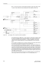
broken wire or voltage failure is recognised or voltage transformer protection breaker
failure (via the respective binary input) is indicated (see also Subsection "Technical
Data").
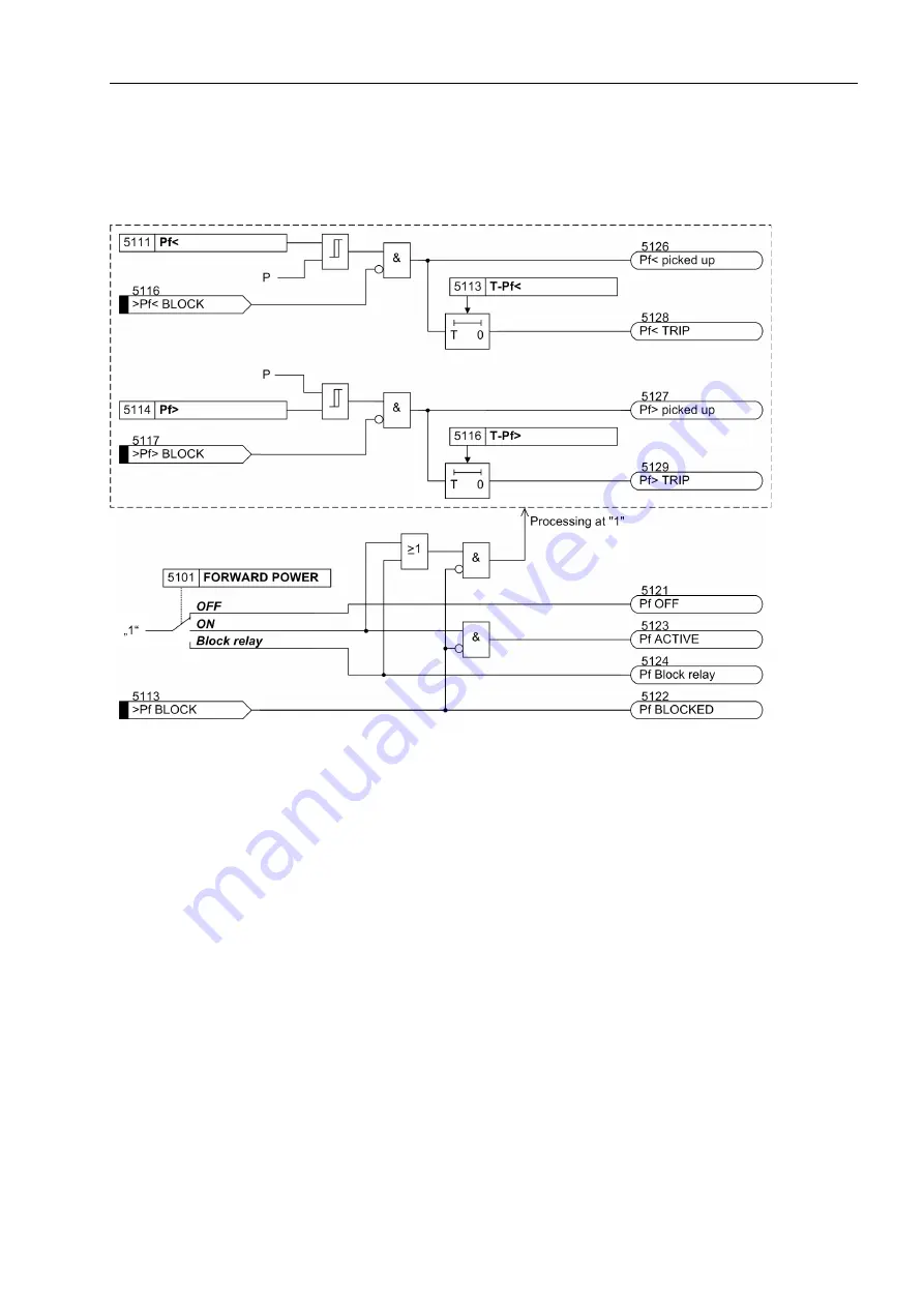
Figure 2-103
Logic diagram of the forward active power supervision
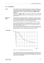
2.13.2 Setting Notes
General
The application of forward power monitoring is only possible in 3-phase protected ob-
jects. It can only be assigned to a side of the main protected object or another mea-
suring location. Furthermore, it is a prerequisite that the device is connected to a three-
phase voltage transformer set, that permits a sensible calculation of the active power
with the respective current transformer connection.
The forward power monitoring can only be effective and is only accessible if it has
been set during configuration under address
151
FORWARD POWER
=
Enabled
(sec-
tion 2.1.3).
Under address
5101
FORWARD POWER
the forward power monitoring can be switched
ON
or
OFF
. Furthermore, the command can be blocked during enabled monitoring
function (
Block relay
).
Pickup Values
For undershooting of a preset active power and the exceeding of another preset active
power, one pickup value each must be set.
If the forward power monitoring has been assigned to a side of the protected object,
the pickup value can be set directly as reference value (with reference to the nominal
Содержание SIPROTEC 7UT613 series
Страница 16: ...Contents 16 7UT613 63x Manual C53000 G1176 C160 2 Literature 631 Glossary 623 Index 633 ...
Страница 30: ...1 Introduction 30 7UT613 63x Manual C53000 G1176 C160 2 ...
Страница 506: ...A Appendix 506 7UT613 63x Manual C53000 G1176 C160 2 7UT633 D E ...
Страница 508: ...A Appendix 508 7UT613 63x Manual C53000 G1176 C160 2 7UT633 P Q ...
Страница 510: ...A Appendix 510 7UT613 63x Manual C53000 G1176 C160 2 7UT635 D E ...
Страница 512: ...A Appendix 512 7UT613 63x Manual C53000 G1176 C160 2 7UT635 P Q ...
Страница 515: ...A 2 Terminal Assignments 515 7UT613 63x Manual C53000 G1176 C160 2 7UT633 B ...
Страница 516: ...A Appendix 516 7UT613 63x Manual C53000 G1176 C160 2 7UT633 B Figure A 7 General diagram 7UT633 panel surface mounting ...
Страница 517: ...A 2 Terminal Assignments 517 7UT613 63x Manual C53000 G1176 C160 2 7UT633 N ...
Страница 518: ...A Appendix 518 7UT613 63x Manual C53000 G1176 C160 2 7UT633 N Figure A 8 General diagram 7UT633 panel surface mounting ...
Страница 519: ...A 2 Terminal Assignments 519 7UT613 63x Manual C53000 G1176 C160 2 7UT635 B ...
Страница 520: ...A Appendix 520 7UT613 63x Manual C53000 G1176 C160 2 7UT635 B Figure A 9 General diagram 7UT635 panel surface mounting ...
Страница 521: ...A 2 Terminal Assignments 521 7UT613 63x Manual C53000 G1176 C160 2 7UT635 N ...
Страница 522: ...A Appendix 522 7UT613 63x Manual C53000 G1176 C160 2 7UT635 N Figure A 10 General diagram 7UT635 panel surface mounting ...
Страница 622: ...A Appendix 622 7UT613 63x Manual C53000 G1176 C160 2 ...
Страница 632: ...Literature 632 7UT613 63x Manual C53000 G1176 C160 2 ...


