


2 Functions
152
7UT613/63x Manual
C53000-G1176-C160-2
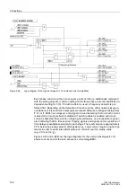
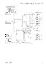
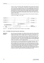
Figure 2-66
Logic diagram of the high-set stages I>> for residual current (simplified)
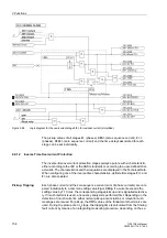
Each phase current and the zero sequence current 3·I0 are, additionally, compared
with the setting value
I>
(common setting for the three phase currents) and
3I0>
(in-
dependent setting for 3·I0). If inrush restraint is used, a frequency analysis is per-
formed first. Depending on the detection of inrush currents, either normal pickup an-
nunciations or relevant inrush messages are issued. After user-configured delay times
T I>
or
T 3I0>
have elapsed, a trip signal is issued assuming that no inrush current
is detected or inrush restraint is disabled. If inrush restraint is enabled and inrush
current is detected, there will be no tripping. Nevertheless, an annunciation is gener-
ated indicating that the time expired. Tripping signals and signals on the expiration of
time delay are available separately for each stage. The reset values are approximately
95 % below the pickup value for settings above
I
N
. Lower values require a higher hys-
teresis in order to avoid intermittent pickup on currents near the pickup value
(e.g. 20 % at 0.2 ·
I
N
).
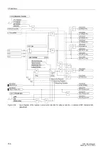
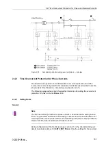
Figures 2-67 and 2-68 show the logic diagrams for the overcurrent stages
I>
for
phase currents and for the zero sequence current stage
3I0>
.
Содержание SIPROTEC 7UT613 series
Страница 16: ...Contents 16 7UT613 63x Manual C53000 G1176 C160 2 Literature 631 Glossary 623 Index 633 ...
Страница 30: ...1 Introduction 30 7UT613 63x Manual C53000 G1176 C160 2 ...
Страница 506: ...A Appendix 506 7UT613 63x Manual C53000 G1176 C160 2 7UT633 D E ...
Страница 508: ...A Appendix 508 7UT613 63x Manual C53000 G1176 C160 2 7UT633 P Q ...
Страница 510: ...A Appendix 510 7UT613 63x Manual C53000 G1176 C160 2 7UT635 D E ...
Страница 512: ...A Appendix 512 7UT613 63x Manual C53000 G1176 C160 2 7UT635 P Q ...
Страница 515: ...A 2 Terminal Assignments 515 7UT613 63x Manual C53000 G1176 C160 2 7UT633 B ...
Страница 516: ...A Appendix 516 7UT613 63x Manual C53000 G1176 C160 2 7UT633 B Figure A 7 General diagram 7UT633 panel surface mounting ...
Страница 517: ...A 2 Terminal Assignments 517 7UT613 63x Manual C53000 G1176 C160 2 7UT633 N ...
Страница 518: ...A Appendix 518 7UT613 63x Manual C53000 G1176 C160 2 7UT633 N Figure A 8 General diagram 7UT633 panel surface mounting ...
Страница 519: ...A 2 Terminal Assignments 519 7UT613 63x Manual C53000 G1176 C160 2 7UT635 B ...
Страница 520: ...A Appendix 520 7UT613 63x Manual C53000 G1176 C160 2 7UT635 B Figure A 9 General diagram 7UT635 panel surface mounting ...
Страница 521: ...A 2 Terminal Assignments 521 7UT613 63x Manual C53000 G1176 C160 2 7UT635 N ...
Страница 522: ...A Appendix 522 7UT613 63x Manual C53000 G1176 C160 2 7UT635 N Figure A 10 General diagram 7UT635 panel surface mounting ...
Страница 622: ...A Appendix 622 7UT613 63x Manual C53000 G1176 C160 2 ...
Страница 632: ...Literature 632 7UT613 63x Manual C53000 G1176 C160 2 ...


