


A Appendix
500
7UT613/63x Manual
C53000-G1176-C160-2
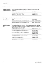
1)
Not possible with surface mounting housing (position 9 = B). For the surface mounted version, please order a device
with the appropriate electrical RS485 interface and accessories in accordance with A.1 under „External Converters“
1)
Not possible with surface mounting housing (position 9 = B). For the surface mounted version, please order a device
with the appropriate electrical RS485 interface and accessories in accordance with A.1 under „External Converters“
2)
Cannot be delivered in connection with 9th digit = B.
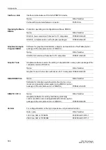
1)
In case of a connection to a RTD box 7XV5662-xAD10, a RS485-LWL converter 7XV5650-0xA00 is required.
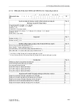
System Interfaces (rear side, port B)
Pos. 11
IEC 60870-5-103 protocol, electrical RS232
1
IEC 60870-5-103 protocol, electrical RS485
2
IEC 60870-5-103 protocol, optical 820 nm, ST connector
3
Profibus FMS Slave, electrical RS485
4
Profibus FMS slave, optical, single ring, ST connector
5
Profibus FMS slave, optical, double ring, ST connector
6
For more interface options see Additional Specification
L
9
Additional Specification L for Further System Interfaces (device rear port B)
(only if Pos. 11 = 9)
Pos. 21
Pos. 22
PROFIBUS DP Slave, RS485
0
A
Profibus DP slave, optical 820 nm, double ring, ST connector
0
B
Modbus, RS485
0
D
Modbus, 820 nm, optical, ST connector
0
E
DNP3.0, RS485
0
G
DNP3.0, optical, 820 nm, ST connector
0
H
IEC 61,850, 100 Mbit Ethernet, double electrical, RJ 45-connector
0
R
IEC 61,850, 100 Mbit Ethernet, optical, ST-connector
0
S
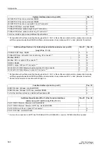
Function Interface (rear side, port C)
Pos. 12
DIGSI / Modem / Browser, electrical RS232
1
DIGSI / Modem / Browser / RTD-box, electrical RS485
2
For further interface options see Additional Specification
M
9
Additional Specification M for Further Function Interfaces
(device rear port C and D) (only if Pos. 12 = 9)
Pos. 23
Pos. 24
Port C: DIGSI / Modem / Browser, electrical RS232
1
Port C: DIGSI / Modem / Browser / RTD-box, electrical RS485
2
Port D: RTD box, 820 nm, optical, ST connector
A
Port D: RTD-Box, electrical RS485
F
Содержание SIPROTEC 7UT613 series
Страница 16: ...Contents 16 7UT613 63x Manual C53000 G1176 C160 2 Literature 631 Glossary 623 Index 633 ...
Страница 30: ...1 Introduction 30 7UT613 63x Manual C53000 G1176 C160 2 ...
Страница 506: ...A Appendix 506 7UT613 63x Manual C53000 G1176 C160 2 7UT633 D E ...
Страница 508: ...A Appendix 508 7UT613 63x Manual C53000 G1176 C160 2 7UT633 P Q ...
Страница 510: ...A Appendix 510 7UT613 63x Manual C53000 G1176 C160 2 7UT635 D E ...
Страница 512: ...A Appendix 512 7UT613 63x Manual C53000 G1176 C160 2 7UT635 P Q ...
Страница 515: ...A 2 Terminal Assignments 515 7UT613 63x Manual C53000 G1176 C160 2 7UT633 B ...
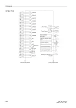
Страница 516: ...A Appendix 516 7UT613 63x Manual C53000 G1176 C160 2 7UT633 B Figure A 7 General diagram 7UT633 panel surface mounting ...
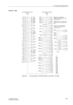
Страница 517: ...A 2 Terminal Assignments 517 7UT613 63x Manual C53000 G1176 C160 2 7UT633 N ...
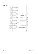
Страница 518: ...A Appendix 518 7UT613 63x Manual C53000 G1176 C160 2 7UT633 N Figure A 8 General diagram 7UT633 panel surface mounting ...
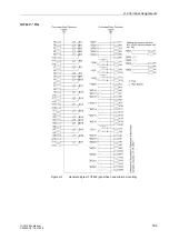
Страница 519: ...A 2 Terminal Assignments 519 7UT613 63x Manual C53000 G1176 C160 2 7UT635 B ...
Страница 520: ...A Appendix 520 7UT613 63x Manual C53000 G1176 C160 2 7UT635 B Figure A 9 General diagram 7UT635 panel surface mounting ...
Страница 521: ...A 2 Terminal Assignments 521 7UT613 63x Manual C53000 G1176 C160 2 7UT635 N ...
Страница 522: ...A Appendix 522 7UT613 63x Manual C53000 G1176 C160 2 7UT635 N Figure A 10 General diagram 7UT635 panel surface mounting ...
Страница 622: ...A Appendix 622 7UT613 63x Manual C53000 G1176 C160 2 ...
Страница 632: ...Literature 632 7UT613 63x Manual C53000 G1176 C160 2 ...


