


A Appendix
562
7UT613/63x Manual
C53000-G1176-C160-2
723
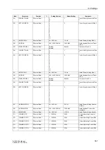
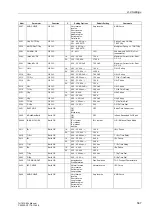
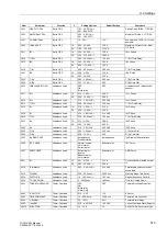
IN-SEC CT IX2
P.System Data 1
1A
5A
1A
CT rated secondary current IX2
731
EARTH IX3 AT
P.System Data 1
Terminal R7
Terminal R8
Terminal R7
Earthing electrod IX3 connected
to
732
IN-PRI CT IX3
P.System Data 1
1 .. 100000 A
200 A
CT rated primary current IX3
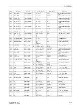
733
IN-SEC CT IX3
P.System Data 1
1A
5A
1A
CT rated secondary current IX3
734
FACTOR CT IX3
P.System Data 1
1.0 .. 300.0
60.0
Factor: prim. over sek. current
IX3
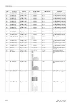
741
EARTH IX4 AT
P.System Data 1
Terminal P7
Terminal P8
Terminal P7
Earthing electrod IX4 connected
to
742
IN-PRI CT IX4
P.System Data 1
1 .. 100000 A
200 A
CT rated primary current IX4
743
IN-SEC CT IX4
P.System Data 1
1A
5A
1A
CT rated secondary current IX4
744
FACTOR CT IX4
P.System Data 1
1.0 .. 300.0
60.0
Factor: prim. over sek. current
IX4
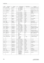
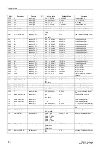
801
UN-PRI VT SET
P.System Data 1
1.0 .. 1200.0 kV
110.0 kV
VT Rated Prim. Voltage Set UL1,
UL2, UL3
802
UN-SEC VT SET
P.System Data 1
80 .. 125 V
100 V
VT Rated Sec. Voltage Set UL1,
UL2, UL3
803
CORRECT. U Ang
P.System Data 1
-5.00 .. 5.00
°
0.00
°
Angle correction UL1, UL2, UL3 -
VT
811
UN-PRI VT U4
P.System Data 1
1.0 .. 1200.0 kV
110.0 kV
VT Rated Primary Voltage U4
812
UN-SEC VT U4
P.System Data 1
80 .. 125 V
100 V
VT Rated Secondary Voltage U4
816
Uph / Udelta
P.System Data 1
0.10 .. 9.99
1.73
Matching ratio Phase-VT to
Open-Delta-VT
817
Uph(U4)/Udelta
P.System Data 1
0.10 .. 9.99
1.73
Matching ratio Ph-VT(U4) to
Open-DeltaVT
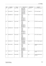
831
SwitchgCBaux S1
P.System Data 1
(Setting options depend
on configuration)
Q0
Switchgear / CBaux at Side 1
832
SwitchgCBaux S2
P.System Data 1
(Setting options depend
on configuration)
None
Switchgear / CBaux at Side 2
833
SwitchgCBaux S3
P.System Data 1
(Setting options depend
on configuration)
None
Switchgear / CBaux at Side 3
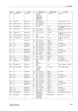
834
SwitchgCBaux S4
P.System Data 1
(Setting options depend
on configuration)
None
Switchgear / CBaux at Side 4
835
SwitchgCBaux S5
P.System Data 1
(Setting options depend
on configuration)
None
Switchgear / CBaux at Side 5
836
SwitchgCBaux M1
P.System Data 1
(Setting options depend
on configuration)
None
Switchgear / CBaux at Measur-
ing Loc. M1
837
SwitchgCBaux M2
P.System Data 1
(Setting options depend
on configuration)
None
Switchgear / CBaux at Measur-
ing Loc. M2
838
SwitchgCBaux M3
P.System Data 1
(Setting options depend
on configuration)
None
Switchgear / CBaux at Measur-
ing Loc. M3
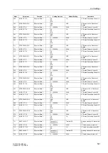
839
SwitchgCBaux M4
P.System Data 1
(Setting options depend
on configuration)
None
Switchgear / CBaux at Measur-
ing Loc. M4
840
SwitchgCBaux M5
P.System Data 1
(Setting options depend
on configuration)
None
Switchgear / CBaux at Measur-
ing Loc. M5
841
SwitchgCBaux E1
P.System Data 1
(Setting options depend
on configuration)
None
Switchgear / CBaux at ext. loca-
tion 1
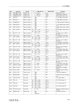
851A
TMin TRIP CMD
P.System Data 1
0.01 .. 32.00 sec
0.15 sec
Minimum TRIP Command Dura-
tion
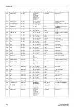
901
WAVEFORMTRIGGER
Osc. Fault Rec.
Save w. Pickup
Save w. TRIP
Start w. TRIP
Save w. Pickup
Waveform Capture
903
MAX. LENGTH
Osc. Fault Rec.
0.30 .. 5.00 sec
1.00 sec
Max. length of a Waveform
Capture Record
904
PRE. TRIG. TIME
Osc. Fault Rec.
0.05 .. 0.50 sec
0.10 sec
Captured Waveform Prior to
Trigger
905
POST REC. TIME
Osc. Fault Rec.
0.05 .. 0.50 sec
0.10 sec
Captured Waveform after Event
906
BinIn CAPT.TIME
Osc. Fault Rec.
0.10 .. 5.00 sec;
∞
0.50 sec
Capture Time via Binary Input
1107
P,Q sign
P.System Data 2
not reversed
reversed
not reversed
sign of P,Q
Addr.
Parameter
Function
C
Setting Options
Default Setting
Comments
Содержание SIPROTEC 7UT613 series
Страница 16: ...Contents 16 7UT613 63x Manual C53000 G1176 C160 2 Literature 631 Glossary 623 Index 633 ...
Страница 30: ...1 Introduction 30 7UT613 63x Manual C53000 G1176 C160 2 ...
Страница 506: ...A Appendix 506 7UT613 63x Manual C53000 G1176 C160 2 7UT633 D E ...
Страница 508: ...A Appendix 508 7UT613 63x Manual C53000 G1176 C160 2 7UT633 P Q ...
Страница 510: ...A Appendix 510 7UT613 63x Manual C53000 G1176 C160 2 7UT635 D E ...
Страница 512: ...A Appendix 512 7UT613 63x Manual C53000 G1176 C160 2 7UT635 P Q ...
Страница 515: ...A 2 Terminal Assignments 515 7UT613 63x Manual C53000 G1176 C160 2 7UT633 B ...
Страница 516: ...A Appendix 516 7UT613 63x Manual C53000 G1176 C160 2 7UT633 B Figure A 7 General diagram 7UT633 panel surface mounting ...
Страница 517: ...A 2 Terminal Assignments 517 7UT613 63x Manual C53000 G1176 C160 2 7UT633 N ...
Страница 518: ...A Appendix 518 7UT613 63x Manual C53000 G1176 C160 2 7UT633 N Figure A 8 General diagram 7UT633 panel surface mounting ...
Страница 519: ...A 2 Terminal Assignments 519 7UT613 63x Manual C53000 G1176 C160 2 7UT635 B ...
Страница 520: ...A Appendix 520 7UT613 63x Manual C53000 G1176 C160 2 7UT635 B Figure A 9 General diagram 7UT635 panel surface mounting ...
Страница 521: ...A 2 Terminal Assignments 521 7UT613 63x Manual C53000 G1176 C160 2 7UT635 N ...
Страница 522: ...A Appendix 522 7UT613 63x Manual C53000 G1176 C160 2 7UT635 N Figure A 10 General diagram 7UT635 panel surface mounting ...
Страница 622: ...A Appendix 622 7UT613 63x Manual C53000 G1176 C160 2 ...
Страница 632: ...Literature 632 7UT613 63x Manual C53000 G1176 C160 2 ...


