


2 Functions
232
7UT613/63x Manual
C53000-G1176-C160-2
2.10
RTD-Boxes for Overload Detection
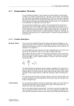
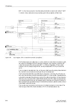
For thermal overload protection, taking into consideration the ambient or coolant tem-
perature as well as the overload protection with hot-spot calculation and relative
ageing rate determination, the coolant temperature in the protected object or the tem-
perature of the hottest spot of the winding (e.g. of a transformer) is required. At least
one resistance temperature detector (RTD) must be installed at the hot-spot location
which informs the device about this temperature via an RTD box 7XV5662-xAD. One
RTD box is able to process up to 6 RTDs. One or two RTD boxes 7XV5662-xAD can
be connected to the device.
2.10.1 Function Description
One RTD box 7XV5662-xAD can be used for up to 6 measuring points (RTDs) in the
protected object, e.g. in the transformer tank. The RTD box detects the coolant tem-
perature of each measuring point from the resistance value of the temperature detec-
tors (Pt 100, Ni 100 or Ni 120) connected with a two- or three-wire line and converts it
to a digital value. The digital values are output at the serial interface RS485.
One or two RTD boxes can be connected to the service interface of the 7UT613/63x.
Thus, up to 6 or 12 measuring points (RTDs) can be processed. For each temperature
detector, characteristic data as well as alarm (stage 1) and trip (stage 2) can be set.
The RTD box also acquires thresholds of each single measuring point. The informa-
tion is then passed on via an output relay. For further information, refer to the instruc-
tion manual of the RTD box.
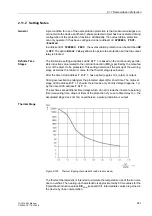
2.10.2 Setting Notes
General
Set the type of temperature detector for RTD 1 (temperature sensor for measuring
point 1) at address
9011
RTD 1 TYPE
. You can choose between
Pt 100
Ω
,
Ni 120
Ω
and
Ni 100
Ω
. If no temperature detector is available for RTD 1, set
RTD 1 TYPE
=
Not connected
. This parameter can only be set with DIGSI under
Additional Set-
tings
.
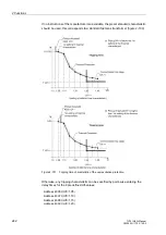
Address
9012
RTD 1 LOCATION
informs the device regarding the mounting location
of RTD 1. You can choose between
Oil
,
Ambient
,
Winding
,
Bearing
and
Other
.
This parameter can only be set with DIGSI under
Additional Settings
.
Furthermore, in the 7UT613/63x an alarm temperature (stage 1) and a tripping tem-
perature (stage 2) can be set. Depending on the temperature unit selected in the
power system data in address
276
TEMP. UNIT
, the alarm temperature can be se-
lected in degree Celsius (
°
C) in address
9013
RTD 1 STAGE 1
or in degree Fahren-
heit (
°
F) in address
9014
RTD 1 STAGE 1
. The trip temperature expressed in Celsius
(
°
C) is set in address
9015
RTD 1 STAGE 2
, and under address
9016
RTD 1 STAGE
2
it can be set in degree Fahrenheit (
°
F) .
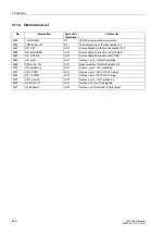
Temperature Detec-
tors
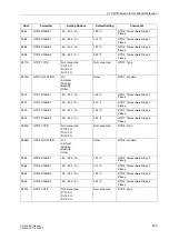
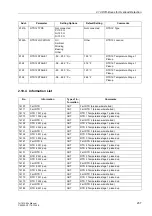
The setting options and addresses of all connected temperature detectors for the first
and the second RTD-box are listed in the following parameter overview.
Содержание SIPROTEC 7UT613 series
Страница 16: ...Contents 16 7UT613 63x Manual C53000 G1176 C160 2 Literature 631 Glossary 623 Index 633 ...
Страница 30: ...1 Introduction 30 7UT613 63x Manual C53000 G1176 C160 2 ...
Страница 506: ...A Appendix 506 7UT613 63x Manual C53000 G1176 C160 2 7UT633 D E ...
Страница 508: ...A Appendix 508 7UT613 63x Manual C53000 G1176 C160 2 7UT633 P Q ...
Страница 510: ...A Appendix 510 7UT613 63x Manual C53000 G1176 C160 2 7UT635 D E ...
Страница 512: ...A Appendix 512 7UT613 63x Manual C53000 G1176 C160 2 7UT635 P Q ...
Страница 515: ...A 2 Terminal Assignments 515 7UT613 63x Manual C53000 G1176 C160 2 7UT633 B ...
Страница 516: ...A Appendix 516 7UT613 63x Manual C53000 G1176 C160 2 7UT633 B Figure A 7 General diagram 7UT633 panel surface mounting ...
Страница 517: ...A 2 Terminal Assignments 517 7UT613 63x Manual C53000 G1176 C160 2 7UT633 N ...
Страница 518: ...A Appendix 518 7UT613 63x Manual C53000 G1176 C160 2 7UT633 N Figure A 8 General diagram 7UT633 panel surface mounting ...
Страница 519: ...A 2 Terminal Assignments 519 7UT613 63x Manual C53000 G1176 C160 2 7UT635 B ...
Страница 520: ...A Appendix 520 7UT613 63x Manual C53000 G1176 C160 2 7UT635 B Figure A 9 General diagram 7UT635 panel surface mounting ...
Страница 521: ...A 2 Terminal Assignments 521 7UT613 63x Manual C53000 G1176 C160 2 7UT635 N ...
Страница 522: ...A Appendix 522 7UT613 63x Manual C53000 G1176 C160 2 7UT635 N Figure A 10 General diagram 7UT635 panel surface mounting ...
Страница 622: ...A Appendix 622 7UT613 63x Manual C53000 G1176 C160 2 ...
Страница 632: ...Literature 632 7UT613 63x Manual C53000 G1176 C160 2 ...


