


2 Functions
144
7UT613/63x Manual
C53000-G1176-C160-2
1. Through-fault current on an external earth fault:
3
I
0
" is in phase opposition with 3
I
0
' and of equal magnitude, i.e 3
I
0
" = –3
I
0
'
I
from
= |3
I
0
'|
I
stab
= |3
I
0
' + 3
I
0
'| – |3
I
0
' – 3
I
0
'| = 2 · |3
I
0
'|
The tripping effect current (
I
from
) equals the starpoint current; the restraining quan-
tity (
I
stab
) is double the size.
2. Internal earth fault, fed only from the starpoint
In this case 3
I
0
" = 0
I
from
= |3
I
0
'|
I
stab
= |3
I
0
' – 0| – |3
I
0
' + 0| = 0
The tripping effect current (
I
from
) equals the starpoint current, the restraining quan-
tity (
I
stab
) is zero, i.e. full sensitivity during internal earth fault.
3. Internal earth fault, fed from the starpoint and from the system, e.g. with equal
earth current magnitude:
In this case 3
I
0
" = 3
I
0
'
I
from
= |3
I
0
'|
I
stab
= |3
I
0
' – 3
I
0
'| – |3
I
0
' + 3
I
0
'| = –2 · |3
I
0
'|
The tripping effect (
I
REF
) equals the starpoint current; the restraining quantity (
I
stab
)
is negative and therefore set to zero, i.e. full sensitivity during internal earth fault.
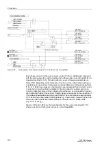
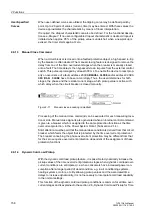
This result shows that for an internal fault no restraint is effective since the restraining
quantity is either zero or negative. Thus, small earth current can cause tripping. In con-
trast, strong restraint becomes effective for external earth faults. Figure 2-60 shows
that the restraint is the strongest when the residual current from the phase current
transformers is high (area with negative 3
I
0
"/3
I
0
'). With ideal current transformers, 3
I
0
"
and 3
I
0
' opposite and equal, i.e. 3
I
0
"/3
I
'0
= –1.
If the starpoint current transformer is designed weaker than the phase current trans-
formers (e.g. by selection of a smaller accuracy limit factor or by higher secondary bur-
den), no trip will be possible under through-fault condition even in case of severe sat-
uration as the magnitude of 3
I
0
" (negative) is always higher than that of 3
I
0
'.
Figure 2-60
Tripping characteristic of the restricted earth fault protection depending on the
earth current ratio 3
I
0
”/3
I
0
' (both currents in phase + or counter-phase –);
I
REF
> = setting;
I
from
= tripping current
Содержание SIPROTEC 7UT613 series
Страница 16: ...Contents 16 7UT613 63x Manual C53000 G1176 C160 2 Literature 631 Glossary 623 Index 633 ...
Страница 30: ...1 Introduction 30 7UT613 63x Manual C53000 G1176 C160 2 ...
Страница 506: ...A Appendix 506 7UT613 63x Manual C53000 G1176 C160 2 7UT633 D E ...
Страница 508: ...A Appendix 508 7UT613 63x Manual C53000 G1176 C160 2 7UT633 P Q ...
Страница 510: ...A Appendix 510 7UT613 63x Manual C53000 G1176 C160 2 7UT635 D E ...
Страница 512: ...A Appendix 512 7UT613 63x Manual C53000 G1176 C160 2 7UT635 P Q ...
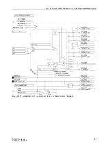
Страница 515: ...A 2 Terminal Assignments 515 7UT613 63x Manual C53000 G1176 C160 2 7UT633 B ...
Страница 516: ...A Appendix 516 7UT613 63x Manual C53000 G1176 C160 2 7UT633 B Figure A 7 General diagram 7UT633 panel surface mounting ...
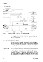
Страница 517: ...A 2 Terminal Assignments 517 7UT613 63x Manual C53000 G1176 C160 2 7UT633 N ...
Страница 518: ...A Appendix 518 7UT613 63x Manual C53000 G1176 C160 2 7UT633 N Figure A 8 General diagram 7UT633 panel surface mounting ...
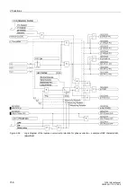
Страница 519: ...A 2 Terminal Assignments 519 7UT613 63x Manual C53000 G1176 C160 2 7UT635 B ...
Страница 520: ...A Appendix 520 7UT613 63x Manual C53000 G1176 C160 2 7UT635 B Figure A 9 General diagram 7UT635 panel surface mounting ...
Страница 521: ...A 2 Terminal Assignments 521 7UT613 63x Manual C53000 G1176 C160 2 7UT635 N ...
Страница 522: ...A Appendix 522 7UT613 63x Manual C53000 G1176 C160 2 7UT635 N Figure A 10 General diagram 7UT635 panel surface mounting ...
Страница 622: ...A Appendix 622 7UT613 63x Manual C53000 G1176 C160 2 ...
Страница 632: ...Literature 632 7UT613 63x Manual C53000 G1176 C160 2 ...


