


2.1 General
73
7UT613/63x Manual
C53000-G1176-C160-2
Similar applies for the further measuring locations (assigned or non-assigned to the
main protected object). Only those addresses will appear during setting which are
available in the actual device version.
Measuring Location 2
• Address
521
STRPNT->OBJ M2
starpoint position of CTs for measuring location
M2,
• Address
522
IN-PRI CT M2
prim. rated current of CTs for measuring location M2,
• Address
523
IN-SEC CT M2
sec. nominal current CT for measuring location M2,
Measuring Location 3
• Address
531
STRPNT->OBJ M3
starpoint position of CT for measuring location M3,
• Address
532
IN-PRI CT M3
prim. rated current of CTs for measuring location M3,
• Address
533
IN-SEC CT M3
sec. nominal current CT for measuring location M3,
Measuring Location 4
• Address
541
STRPNT->OBJ M4
starpoint position of CT for measuring location M4,
• Address
542
IN-PRI CT M4
prim. rated current of CTs for measuring location M4,
• Address
543
IN-SEC CT M4
sec.. rated current of CTs for measuring location M4.
Measuring Location 5
• Address
551
STRPNT->OBJ M5
starpoint position of CTs for measuring location
M5,
• Address
552
IN-PRI CT M5
prim. rated current of CTs for measuring location M5,
• Address
553
IN-SEC CT M5
sec. nominal current CT for measuring location M5,
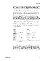
If the device is applied as transverse differential protection for generators or motors,
special considerations must be observed for the CT connections: In a healthy opera-
tional state all currents flow into the protected object, i.e. in contrast to the other appli-
cations. Therefore you have to set a „wrong“ polarity for one of the current transformer
sets. The part windings of the machine windings correspond to the „sides“.
One example is illustrated in figure 2-14. Although the starpoints of both current trans-
former sets are looking towards the protected object, the opposite setting is to be se-
lected for “side 2”:
STRPNT->OBJ M2
=
NO
.
Figure 2-14
Current transformer starpoints in transverse differential protection - example
Содержание SIPROTEC 7UT613 series
Страница 16: ...Contents 16 7UT613 63x Manual C53000 G1176 C160 2 Literature 631 Glossary 623 Index 633 ...
Страница 30: ...1 Introduction 30 7UT613 63x Manual C53000 G1176 C160 2 ...
Страница 506: ...A Appendix 506 7UT613 63x Manual C53000 G1176 C160 2 7UT633 D E ...
Страница 508: ...A Appendix 508 7UT613 63x Manual C53000 G1176 C160 2 7UT633 P Q ...
Страница 510: ...A Appendix 510 7UT613 63x Manual C53000 G1176 C160 2 7UT635 D E ...
Страница 512: ...A Appendix 512 7UT613 63x Manual C53000 G1176 C160 2 7UT635 P Q ...
Страница 515: ...A 2 Terminal Assignments 515 7UT613 63x Manual C53000 G1176 C160 2 7UT633 B ...
Страница 516: ...A Appendix 516 7UT613 63x Manual C53000 G1176 C160 2 7UT633 B Figure A 7 General diagram 7UT633 panel surface mounting ...
Страница 517: ...A 2 Terminal Assignments 517 7UT613 63x Manual C53000 G1176 C160 2 7UT633 N ...
Страница 518: ...A Appendix 518 7UT613 63x Manual C53000 G1176 C160 2 7UT633 N Figure A 8 General diagram 7UT633 panel surface mounting ...
Страница 519: ...A 2 Terminal Assignments 519 7UT613 63x Manual C53000 G1176 C160 2 7UT635 B ...
Страница 520: ...A Appendix 520 7UT613 63x Manual C53000 G1176 C160 2 7UT635 B Figure A 9 General diagram 7UT635 panel surface mounting ...
Страница 521: ...A 2 Terminal Assignments 521 7UT613 63x Manual C53000 G1176 C160 2 7UT635 N ...
Страница 522: ...A Appendix 522 7UT613 63x Manual C53000 G1176 C160 2 7UT635 N Figure A 10 General diagram 7UT635 panel surface mounting ...
Страница 622: ...A Appendix 622 7UT613 63x Manual C53000 G1176 C160 2 ...
Страница 632: ...Literature 632 7UT613 63x Manual C53000 G1176 C160 2 ...


