


2 Functions
56
7UT613/63x Manual
C53000-G1176-C160-2
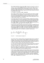
Figure 2-7
Topology of a transformer bank consisting of 3 single-phase auto-transformers,
topology definitions for a current comparison protection for each phase
Sides:
S1
High voltage side of the auto-connected winding of the main protected object
S2
Low voltage side (tap) of the auto-connected winding of the main protected object
S3
Starpoint side of the auto-connected winding of the main protected object
Measuring locations 3-phase, assigned:
M1
Measuring location, assigned to the main protected object, side 1
M2
Measuring location, assigned to the main protected object, side 2
M3
Measuring location, assigned to the main protected object, side 3
Auxiliary measuring locations, 1-phase, assigned to the main object:
X1
Measuring location, assigned to the main protected object, side 1 and 2
Global Data for 1-
Phase Busbar Pro-
tection
If the device is used as busbar protection, either as single-phase protection or as
three-phase protection via external summation transformers, set the number of
feeders of the busbar in address
216
NUMBER OF ENDS
. The minimum number
amounts to
3
ends (with less than that the operation of a 7UT613/63x would not make
sense).
The maximum number of feeders amounts to
9
ends in 7UT613 and 7UT633 and
12
in 7UT635.
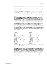
Assignment of 3-
phase Measuring
Locations
After determination of the global data, the 3-phase measuring locations must be as-
signed to the sides of the main protected object. Only few meaningful combinations
are possible for this assignment because of the condition that always
NUMBER OF
SIDES
≤
No AssigMeasLoc
≤
No Conn.MeasLoc
and that a protected object pro-
vides at least 2 sides. In order to exclude impossible combinations at all, only those
addresses of the following lists are requested which correspond to the global settings
of addresses
211
,
212
, and
213
. Furthermore, only meaningful setting options
appear.
Содержание SIPROTEC 7UT613 series
Страница 16: ...Contents 16 7UT613 63x Manual C53000 G1176 C160 2 Literature 631 Glossary 623 Index 633 ...
Страница 30: ...1 Introduction 30 7UT613 63x Manual C53000 G1176 C160 2 ...
Страница 506: ...A Appendix 506 7UT613 63x Manual C53000 G1176 C160 2 7UT633 D E ...
Страница 508: ...A Appendix 508 7UT613 63x Manual C53000 G1176 C160 2 7UT633 P Q ...
Страница 510: ...A Appendix 510 7UT613 63x Manual C53000 G1176 C160 2 7UT635 D E ...
Страница 512: ...A Appendix 512 7UT613 63x Manual C53000 G1176 C160 2 7UT635 P Q ...
Страница 515: ...A 2 Terminal Assignments 515 7UT613 63x Manual C53000 G1176 C160 2 7UT633 B ...
Страница 516: ...A Appendix 516 7UT613 63x Manual C53000 G1176 C160 2 7UT633 B Figure A 7 General diagram 7UT633 panel surface mounting ...
Страница 517: ...A 2 Terminal Assignments 517 7UT613 63x Manual C53000 G1176 C160 2 7UT633 N ...
Страница 518: ...A Appendix 518 7UT613 63x Manual C53000 G1176 C160 2 7UT633 N Figure A 8 General diagram 7UT633 panel surface mounting ...
Страница 519: ...A 2 Terminal Assignments 519 7UT613 63x Manual C53000 G1176 C160 2 7UT635 B ...
Страница 520: ...A Appendix 520 7UT613 63x Manual C53000 G1176 C160 2 7UT635 B Figure A 9 General diagram 7UT635 panel surface mounting ...
Страница 521: ...A 2 Terminal Assignments 521 7UT613 63x Manual C53000 G1176 C160 2 7UT635 N ...
Страница 522: ...A Appendix 522 7UT613 63x Manual C53000 G1176 C160 2 7UT635 N Figure A 10 General diagram 7UT635 panel surface mounting ...
Страница 622: ...A Appendix 622 7UT613 63x Manual C53000 G1176 C160 2 ...
Страница 632: ...Literature 632 7UT613 63x Manual C53000 G1176 C160 2 ...


