


2 Functions
76
7UT613/63x Manual
C53000-G1176-C160-2
Feeder 11
• Address
661
STRPNT->BUS I11
= transformer starpoint versus busbar for feeder
11,
• Address
662
IN-PRI CT I11
= rated primary transformer current for feeder 11,
• Address
663
IN-SEC CT I11
= rated secondary current for feeder 11.
Feeder 12
• Address
671
STRPNT->BUS I12
= transformer starpoint versus busbar for feeder
12,
• Address
672
IN-PRI CT I12
= rated primary transformer current for feeder 12,
• Address
673
IN-SEC CT I12
= rated secondary current for feeder 12.
Current Transform-
er Data for 1-phase
Further Current
Inputs
The number of 1-phase further current inputs depends on the device version. Such
inputs are used for detection of the starpoint current of an earthed winding of a trans-
former, generator, or motor, shunt reactor, or neutral reactor, or for different 1-phase
measuring purposes. The assignment has already been carried out in Subsection
2.1.4, margin heading „Assignment of Auxiliary 1-phase Measuring Locations“, the as-
signment of the protection functions will be done in section „Assignment of the Protec-
tion Functions to the Measuring Locations/Sides“. These settings concern exclusively
the current transformer data, regardless of whether or not they belong to the main pro-
tected object.
The device requests also the polarity and rated currents of the connected 1-phase
CTs. The clarifications below comprise all possible settings, in the actual case only
those addresses will appear which are available in the actual version and defined in
the topology.
Enter the primary rated current of each further 1-phase current transformer which is
connected and assigned to a further 1-phase current input of the device. Please note
the previous assignment of the measuring locations (see section 2.1.4.1, margin
heading „Assignment of Auxiliary 1-phase Measuring Locations“).
Distinction must be made for the secondary rated currents whether the 1-phase
current input is a „normal“ or a „high-sensitivity“ input of the device:
If a „normal“ input is concerned, set the secondary current in the same way as for the
3-phase current inputs. Please make sure that the rated secondary CT current
matches the rated current of the corresponding current input of the device. Rated sec-
ondary currents of the device can be matched.
If a „high-sensitivity“ current input is used, no rated secondary current is defined. In
order to calculate primary values for such measuring inputs (e.g. for setting in primary
values or for output of primary measured values), the conversion factor
I
Nprim
/
I
Nsec
of
the current transformer is set.
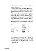
The polarity of a 1-phase current input is important for correct function of the differen-
tial protection and the restricted earth fault protection. If only the magnitude of the
current is of interest (e.g. for earth overcurrent protection or single-phase overcurrent
protection) the polarity is irrelevant, Even though a high-sensitive 1-phase current
input has been selected, the polarity setting is omitted as it only processes the current
amount.
For polarity information, set to which device terminal
the
side of the current transform-
er facing the earth electrode is connected, i.e. not the side facing the starpoint itself.
The secondary earthing point of the CT is of no interest. Figure 2-16 shows the alter-
natives using as an example an earthed transformer winding for auxiliary current
I
X1.
Содержание SIPROTEC 7UT613 series
Страница 16: ...Contents 16 7UT613 63x Manual C53000 G1176 C160 2 Literature 631 Glossary 623 Index 633 ...
Страница 30: ...1 Introduction 30 7UT613 63x Manual C53000 G1176 C160 2 ...
Страница 506: ...A Appendix 506 7UT613 63x Manual C53000 G1176 C160 2 7UT633 D E ...
Страница 508: ...A Appendix 508 7UT613 63x Manual C53000 G1176 C160 2 7UT633 P Q ...
Страница 510: ...A Appendix 510 7UT613 63x Manual C53000 G1176 C160 2 7UT635 D E ...
Страница 512: ...A Appendix 512 7UT613 63x Manual C53000 G1176 C160 2 7UT635 P Q ...
Страница 515: ...A 2 Terminal Assignments 515 7UT613 63x Manual C53000 G1176 C160 2 7UT633 B ...
Страница 516: ...A Appendix 516 7UT613 63x Manual C53000 G1176 C160 2 7UT633 B Figure A 7 General diagram 7UT633 panel surface mounting ...
Страница 517: ...A 2 Terminal Assignments 517 7UT613 63x Manual C53000 G1176 C160 2 7UT633 N ...
Страница 518: ...A Appendix 518 7UT613 63x Manual C53000 G1176 C160 2 7UT633 N Figure A 8 General diagram 7UT633 panel surface mounting ...
Страница 519: ...A 2 Terminal Assignments 519 7UT613 63x Manual C53000 G1176 C160 2 7UT635 B ...
Страница 520: ...A Appendix 520 7UT613 63x Manual C53000 G1176 C160 2 7UT635 B Figure A 9 General diagram 7UT635 panel surface mounting ...
Страница 521: ...A 2 Terminal Assignments 521 7UT613 63x Manual C53000 G1176 C160 2 7UT635 N ...
Страница 522: ...A Appendix 522 7UT613 63x Manual C53000 G1176 C160 2 7UT635 N Figure A 10 General diagram 7UT635 panel surface mounting ...
Страница 622: ...A Appendix 622 7UT613 63x Manual C53000 G1176 C160 2 ...
Страница 632: ...Literature 632 7UT613 63x Manual C53000 G1176 C160 2 ...


