


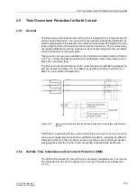


2.4 Time Overcurrent Protection for Phase and Residual Currents
167
7UT613/63x Manual
C53000-G1176-C160-2
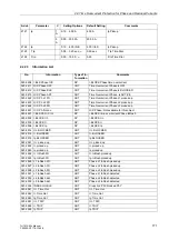
Table 2-7
Preferred values of standardized currents for user-defined
trip characteristics
The default setting of current values is
∞
. They are, therefore, not enabled — and no
pickup or tripping of these protective functions will occur.
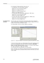
For specification of a tripping characteristic please note the following:
• The value pairs are to be indicated in continuous order. You may also enter less
than 20 value pairs. In most cases, 10 value pairs would be sufficient to be able to
define an exact characteristic. A value pair which will not be used, has to be made
invalid by entering
∞
for the threshold! Please ensure that a clear and steady char-
acteristic is formed by the value pairs.
• For currents select the values from the above table and add the corresponding time
values. Deviating values
I
/
I
p are rounded to the next adjacent value. This, however,
will not be indicated.
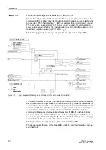
• Currents smaller than the current value of the smallest characteristic point do not
lead to a prolongation of the tripping time. The pickup characteristic (see Figure
2-76, right side) goes parallel to the current axis, up to the smallest characteristic
point.
• Currents greater than the current value of the largest characteristic point do not lead
to a reduction of the tripping time. The pickup characteristic (see Figure 2-76, right
side) goes parallel to the current axis, beginning with the largest characteristic point.
Figure 2-76
User-specified characteristic — example
I
/
I
p
= 1 to 1.94
I
/
I
p
= 2 to 4.75
I
/
I
p
= 5 to 7.75
I
/
I
p
= 8 to 20
1.00
1.50
2.00
3.50
5.00
6.50
8.00
15.00
1.06
1.56
2.25
3.75
5.25
6.75
9.00
16.00
1.13
1.63
2.50
4.00
5.50
7.00
10.00
17.00
1.19
1.69
2.75
4.25
5.75
7.25
11.00
18.00
1.25
1.75
3.00
4.50
6.00
7.50
12.00
19.00
1.31
1.81
3.25
4.75
6.25
7.75
13.00
20.00
1.38
1.88
14.00
1.44
1.94
Содержание SIPROTEC 7UT613 series
Страница 16: ...Contents 16 7UT613 63x Manual C53000 G1176 C160 2 Literature 631 Glossary 623 Index 633 ...
Страница 30: ...1 Introduction 30 7UT613 63x Manual C53000 G1176 C160 2 ...
Страница 506: ...A Appendix 506 7UT613 63x Manual C53000 G1176 C160 2 7UT633 D E ...
Страница 508: ...A Appendix 508 7UT613 63x Manual C53000 G1176 C160 2 7UT633 P Q ...
Страница 510: ...A Appendix 510 7UT613 63x Manual C53000 G1176 C160 2 7UT635 D E ...
Страница 512: ...A Appendix 512 7UT613 63x Manual C53000 G1176 C160 2 7UT635 P Q ...
Страница 515: ...A 2 Terminal Assignments 515 7UT613 63x Manual C53000 G1176 C160 2 7UT633 B ...
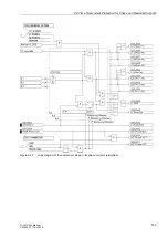
Страница 516: ...A Appendix 516 7UT613 63x Manual C53000 G1176 C160 2 7UT633 B Figure A 7 General diagram 7UT633 panel surface mounting ...
Страница 517: ...A 2 Terminal Assignments 517 7UT613 63x Manual C53000 G1176 C160 2 7UT633 N ...
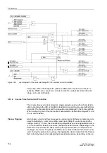
Страница 518: ...A Appendix 518 7UT613 63x Manual C53000 G1176 C160 2 7UT633 N Figure A 8 General diagram 7UT633 panel surface mounting ...
Страница 519: ...A 2 Terminal Assignments 519 7UT613 63x Manual C53000 G1176 C160 2 7UT635 B ...
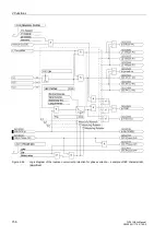
Страница 520: ...A Appendix 520 7UT613 63x Manual C53000 G1176 C160 2 7UT635 B Figure A 9 General diagram 7UT635 panel surface mounting ...
Страница 521: ...A 2 Terminal Assignments 521 7UT613 63x Manual C53000 G1176 C160 2 7UT635 N ...
Страница 522: ...A Appendix 522 7UT613 63x Manual C53000 G1176 C160 2 7UT635 N Figure A 10 General diagram 7UT635 panel surface mounting ...
Страница 622: ...A Appendix 622 7UT613 63x Manual C53000 G1176 C160 2 ...
Страница 632: ...Literature 632 7UT613 63x Manual C53000 G1176 C160 2 ...


