


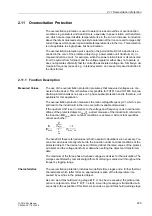


2.11 Overexcitation Protection
241
7UT613/63x Manual
C53000-G1176-C160-2
2.11.2 Setting Notes
General
A precondition for use of the overexcitation protection is that measured voltages are
connected to the device and that a 3-phase protected object has been selected during
configuration of the protection functions. Additionally, the overexcitation protection
can only operate if it has been configured under address
143
OVEREXC. PROT.
=
Enabled
.
In address
4301
OVEREXC. PROT.
, the overexcitation protection can be switched
ON
or
OFF
. The option
Block relay
allows to operate the protection but the trip output
relay is blocked.
Definite Time
Stages
The limit-value setting at address
4302
U/f >
is based on the continuously permis-
sible induction value related to the nominal induction (B/B
N
) specified by the manufac-
turer of the object to be protected. This setting determines the pickup of the warning
stage as well as the minimum value for the thermal stage (see below).
After the time
4303
address
T U/f >
has expired (approx 10 s) alarm is output.
Strong overexcitation endangers the protected object after short time. The high-set
stage
4304
address
U/f >>
should, therefore be only shortly delayed (approx. 1 s)
by the time
4305
address
T U/f >>
.
The set times are additional time delays which do not include the inherent operating
time (measuring time, drop-out time) of the protection. If you set a time delay to
∞
, the
associated stage does not trip; nevertheless, a pickup indication is output.
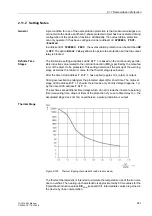
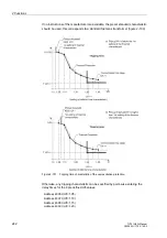
Thermal Stage
Figure 2-100
Thermal tripping characteristic (with preset values)
The thermal characteristic is intended to simulate the temperature rise of the iron core
due to overflux. The heating-up characteristic is approximated by 8 time values for the
8 predefined induction values B/B
NObj
(reduced U/f). Intermediate values are gained in
the device by linear interpolation.
Содержание SIPROTEC 7UT613 series
Страница 16: ...Contents 16 7UT613 63x Manual C53000 G1176 C160 2 Literature 631 Glossary 623 Index 633 ...
Страница 30: ...1 Introduction 30 7UT613 63x Manual C53000 G1176 C160 2 ...
Страница 506: ...A Appendix 506 7UT613 63x Manual C53000 G1176 C160 2 7UT633 D E ...
Страница 508: ...A Appendix 508 7UT613 63x Manual C53000 G1176 C160 2 7UT633 P Q ...
Страница 510: ...A Appendix 510 7UT613 63x Manual C53000 G1176 C160 2 7UT635 D E ...
Страница 512: ...A Appendix 512 7UT613 63x Manual C53000 G1176 C160 2 7UT635 P Q ...
Страница 515: ...A 2 Terminal Assignments 515 7UT613 63x Manual C53000 G1176 C160 2 7UT633 B ...
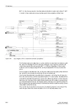
Страница 516: ...A Appendix 516 7UT613 63x Manual C53000 G1176 C160 2 7UT633 B Figure A 7 General diagram 7UT633 panel surface mounting ...
Страница 517: ...A 2 Terminal Assignments 517 7UT613 63x Manual C53000 G1176 C160 2 7UT633 N ...
Страница 518: ...A Appendix 518 7UT613 63x Manual C53000 G1176 C160 2 7UT633 N Figure A 8 General diagram 7UT633 panel surface mounting ...
Страница 519: ...A 2 Terminal Assignments 519 7UT613 63x Manual C53000 G1176 C160 2 7UT635 B ...
Страница 520: ...A Appendix 520 7UT613 63x Manual C53000 G1176 C160 2 7UT635 B Figure A 9 General diagram 7UT635 panel surface mounting ...
Страница 521: ...A 2 Terminal Assignments 521 7UT613 63x Manual C53000 G1176 C160 2 7UT635 N ...
Страница 522: ...A Appendix 522 7UT613 63x Manual C53000 G1176 C160 2 7UT635 N Figure A 10 General diagram 7UT635 panel surface mounting ...
Страница 622: ...A Appendix 622 7UT613 63x Manual C53000 G1176 C160 2 ...
Страница 632: ...Literature 632 7UT613 63x Manual C53000 G1176 C160 2 ...


