


2.22 Additional Functions
305
7UT613/63x Manual
C53000-G1176-C160-2
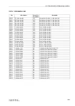
Table 2-12
Operational measured values (magnitudes) of the measuring locations
1)
only for 3-phase objects, also for single-phase transformers
2)
only for 3-phase objects, not for single-phase transformers
3)
only for single-phase busbar protection
4)
only for 7UT613 and 7UT633 with voltage measuring inputs
5)
only for 7UT635
6)
if configured and prepared in CFC
7)
calculated from phase currents and rated voltage or measured voltage U
meas
Measured Values
Primary
Secondary
% referred to
I
L1M1,
I
L2M1,
I
L3M1
I
L1M2,
I
L2M2,
I
L3M2
I
L1M3,
I
L2M3,
I
L3M3
Phase currents at the measuring loca-
tions M1 to M3
A; kA
R
Rated operational current of
the assigned side; if the mea-
suring location is not as-
signed, then
403
..
405
„I
PRIMARY OP M3..5“
I
1M1,
I
2M1, 3
I
0M1
I
1M2,
I
2M2, 3
I
0M2
I
1M3,
I
2M3, 3
I
0M3
Positive, negative and zero sequence
component of the currents at the mea-
suring locations M1 to M3
A; kA
R
I
L1M4,
I
L2M4,
I
L3M4
I
L1M5,
I
L2M5,
I
L3M5
Phase currents at the measuring loca-
tions M4 to M5
A; kA
R
I
1M4,
I
2M4, 3
I
0M4
I
1M5,
I
2M5, 3
I
0M5
Positive, negative and zero sequence
component of the currents at the mea-
suring locations M4 to M5
A; kA
R
I
Z1;
I
Z2;
I
Z3
Currents at the 1-phase further measur-
ing locations X1 to X3
A; kA
R
- if allocated to side
→
see
measured value „
I
LxSy“
- if allocated to measuring lo-
cation
→
see measured
value „
I
LxMz“
- if not allocated
→
then „
I
N-
PRI WDL
I
Z1..4“
I
X4
Current at the further measuring loca-
tion X4
A; kA
R
I
1 to
I
9
Currents at the measuring inputs
A; kA
R
Rated operational current
I
10 to
I
12
Currents at the measuring inputs
A; kA
R
Rated operational current
UL1E; UL2E; UL3E
Phase-to-earth voltages at the 3-phase
voltage measuring location
V; kV;
MV
V
Operational rated voltage/
√
3
UL12; UL23; UL31
Phase-to-phase voltages at the 3-phase
voltage measuring location
V; kV;
MV
V
Operational rated voltage
U1; U2; U0
Positive, negative and zero sequence
component of the voltages at the 3-
phase voltage measuring location
V; kV;
MV
V
Operational rated voltage/
√
3
Uen
Displacement voltage if connected to
the 1-phase voltage measuring input
—
V
Operational rated voltage
U4
Voltage at the 1-phase voltage measur-
ing input
V; kV;
MV
V
Operational rated voltage
S, P, Q
Apparent, active and reactive power
MVA,
MW,
kVA; kW
—
Operational rated apparent
power
f
Frequency
Hz
Hz
Rated frequency
cos
ϕ
Power factor
(abs)
—
(abs)
Umeas
Voltage from the current measured at
the 1-phase measuring input
V; kV;
MV
—
—
S
Apparent power
kVA;
MVA
—
—
U/f
Overexcitation
U
N
/f
N
—
U
N
/f
N
Содержание SIPROTEC 7UT613 series
Страница 16: ...Contents 16 7UT613 63x Manual C53000 G1176 C160 2 Literature 631 Glossary 623 Index 633 ...
Страница 30: ...1 Introduction 30 7UT613 63x Manual C53000 G1176 C160 2 ...
Страница 506: ...A Appendix 506 7UT613 63x Manual C53000 G1176 C160 2 7UT633 D E ...
Страница 508: ...A Appendix 508 7UT613 63x Manual C53000 G1176 C160 2 7UT633 P Q ...
Страница 510: ...A Appendix 510 7UT613 63x Manual C53000 G1176 C160 2 7UT635 D E ...
Страница 512: ...A Appendix 512 7UT613 63x Manual C53000 G1176 C160 2 7UT635 P Q ...
Страница 515: ...A 2 Terminal Assignments 515 7UT613 63x Manual C53000 G1176 C160 2 7UT633 B ...
Страница 516: ...A Appendix 516 7UT613 63x Manual C53000 G1176 C160 2 7UT633 B Figure A 7 General diagram 7UT633 panel surface mounting ...
Страница 517: ...A 2 Terminal Assignments 517 7UT613 63x Manual C53000 G1176 C160 2 7UT633 N ...
Страница 518: ...A Appendix 518 7UT613 63x Manual C53000 G1176 C160 2 7UT633 N Figure A 8 General diagram 7UT633 panel surface mounting ...
Страница 519: ...A 2 Terminal Assignments 519 7UT613 63x Manual C53000 G1176 C160 2 7UT635 B ...
Страница 520: ...A Appendix 520 7UT613 63x Manual C53000 G1176 C160 2 7UT635 B Figure A 9 General diagram 7UT635 panel surface mounting ...
Страница 521: ...A 2 Terminal Assignments 521 7UT613 63x Manual C53000 G1176 C160 2 7UT635 N ...
Страница 522: ...A Appendix 522 7UT613 63x Manual C53000 G1176 C160 2 7UT635 N Figure A 10 General diagram 7UT635 panel surface mounting ...
Страница 622: ...A Appendix 622 7UT613 63x Manual C53000 G1176 C160 2 ...
Страница 632: ...Literature 632 7UT613 63x Manual C53000 G1176 C160 2 ...


