


2 Functions
70
7UT613/63x Manual
C53000-G1176-C160-2
Object Data with
Busbars (1-phase
Connection) with
up to 6 or 9 or 12
Feeders
These busbar data are only required if the device is used for single-phase busbar dif-
ferential protection. When configuring the scope of functions (see Scope of Functions,
address
105
), the following must have been set:
PROT. OBJECT
=
1ph Busbar
. In
cases other than that, these settings are not available. 7UT613 and 7UT633 allow up
to 9, 7UT635 up to 12 feeders.
With address
370
UN BUSBAR
you inform the device of the primary rated voltage
(phase-to-phase). This setting has no effect on the protective functions but influences
the displays of the operational measured values.
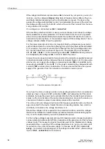
The feeders of a busbar may be rated for different currents. For instance, an overhead
line may be able to carry higher load than a cable feeder or a transformer feeder. You
can define a primary rated current for each feeder of the protected object; this current
will be the reference for all referred values. These ratings may differ from the rated cur-
rents of the associated current transformers which latter will be entered at a later stage
(current transformer data). Figure 2-12 shows the example of a busbar with 3 feeders.
Additionally, a rated current for the entire busbar as the main protected object can be
determined. The currents of all measuring locations assigned to the main object are
converted such that the values of the differential protection are referred to this rated
current of the main protected object, here the busbar. If the current rating of the busbar
is known, set this rated current in address
371
I PRIMARY OP.
. If no rated current
of the busbar is defined, you should select the highest of the rated currents of the sides
(= feeders). In Figure 2-12, the rated object current (busbar current) would be 1000 A.
Under address
381
I PRIMARY OP 1
, set the rated primary current of feeder 1.
The same considerations apply for the further feeders:
• Address
382
I PRIMARY OP 2
for feeder 2,
• Address
383
I PRIMARY OP 3
for feeder 3,
• Address
384
I PRIMARY OP 4
for feeder 4,
• Address
385
I PRIMARY OP 5
for feeder 5,
• Address
386
I PRIMARY OP 6
for feeder 6,
• Address
387
I PRIMARY OP 7
for feeder 7,
• Address
388
I PRIMARY OP 8
for feeder 8,
• Address
389
I PRIMARY OP 9
for feeder 9,
• Address
390
I PRIMARY OP 10
for feeder 10,
• Address
391
I PRIMARY OP 11
for feeder 11,
• Address
392
I PRIMARY OP 12
for feeder 12.
In 7UT613 and 7UT633 addresses
390
to
392
are omitted, since these versions only
permit 9 feeders.
If one 7UT613/63x is used per phase, set the same rated current and voltage of a
feeder for all three devices. For the identification of the phases for fault annunciations
and measured values each device is to be informed on the phase to which it is as-
signed. This is to be set in address
396
PHASE SELECTION
.
Object Data for
Further Protected
Objects
The object data described in the previous paragraphs relate to the main protected
object whose sides and measuring locations have been assigned according to section
2.1.4.1. If you have defined further protected objects in your topology, a number of
non-assigned measuring locations will be left. The rated values of these are requested
now.
The considerations concerning rated voltages and current are the same as for the
main protected object. Only those of the following addresses will appear during setting
Содержание SIPROTEC 7UT613 series
Страница 16: ...Contents 16 7UT613 63x Manual C53000 G1176 C160 2 Literature 631 Glossary 623 Index 633 ...
Страница 30: ...1 Introduction 30 7UT613 63x Manual C53000 G1176 C160 2 ...
Страница 506: ...A Appendix 506 7UT613 63x Manual C53000 G1176 C160 2 7UT633 D E ...
Страница 508: ...A Appendix 508 7UT613 63x Manual C53000 G1176 C160 2 7UT633 P Q ...
Страница 510: ...A Appendix 510 7UT613 63x Manual C53000 G1176 C160 2 7UT635 D E ...
Страница 512: ...A Appendix 512 7UT613 63x Manual C53000 G1176 C160 2 7UT635 P Q ...
Страница 515: ...A 2 Terminal Assignments 515 7UT613 63x Manual C53000 G1176 C160 2 7UT633 B ...
Страница 516: ...A Appendix 516 7UT613 63x Manual C53000 G1176 C160 2 7UT633 B Figure A 7 General diagram 7UT633 panel surface mounting ...
Страница 517: ...A 2 Terminal Assignments 517 7UT613 63x Manual C53000 G1176 C160 2 7UT633 N ...
Страница 518: ...A Appendix 518 7UT613 63x Manual C53000 G1176 C160 2 7UT633 N Figure A 8 General diagram 7UT633 panel surface mounting ...
Страница 519: ...A 2 Terminal Assignments 519 7UT613 63x Manual C53000 G1176 C160 2 7UT635 B ...
Страница 520: ...A Appendix 520 7UT613 63x Manual C53000 G1176 C160 2 7UT635 B Figure A 9 General diagram 7UT635 panel surface mounting ...
Страница 521: ...A 2 Terminal Assignments 521 7UT613 63x Manual C53000 G1176 C160 2 7UT635 N ...
Страница 522: ...A Appendix 522 7UT613 63x Manual C53000 G1176 C160 2 7UT635 N Figure A 10 General diagram 7UT635 panel surface mounting ...
Страница 622: ...A Appendix 622 7UT613 63x Manual C53000 G1176 C160 2 ...
Страница 632: ...Literature 632 7UT613 63x Manual C53000 G1176 C160 2 ...


