


2 Functions
200
7UT613/63x Manual
C53000-G1176-C160-2
For protection against overvoltages it is also important that the device is directly con-
nected to the earthed side of the current transformers so that the high voltage at the
resistor can be kept away from the device.
For generators, motors and shunt reactors high-impedance differential protection can
be used analogously. All current transformers at the overvoltage side, the undervolt-
age side and the current transformer at the starpoint have to be connected in parallel
when using auto-transformers.
In principle, this scheme can be applied to every protected object. When applied as
busbar protection, for example, the device is connected to the parallel connection of
all feeder current transformers via the resistor.
2.7.3
Tank Leakage Protection
Application
Example
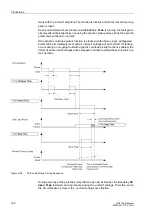
The tank leakage protection has the task to detect earth leakage — even high-ohmic
— between a phase and the frame of a power transformer. The tank must be isolated
from earth. A conductor links the tank to earth, and the current through this conductor
is fed to a current input of the relay. When a tank leakage occurs, a fault current (tank
leakage current) will flow through the earthing conductor to earth. This tank leakage
current is detected by the single-phase overcurrent protection as an overcurrent; an
instantaneous or delayed trip command is issued in order to disconnect all sides of the
transformer.
A high-sensitivity single-phase current input is used for tank leakage protection.
Figure 2-89
Principle of tank leakage protection
2.7.4
Setting Notes
General
the single-phase time overcurrent protection can switched at address
2701
1Phase
O/C
ON
or
OFF
. The option
Block relay
allows to operate the protection but the trip
output relay is blocked.
The settings depend on the application. The setting ranges depend on whether a "nor-
mal" or a "high-sensitivity" current input is used. This was determined during assign-
ment of the protection function (section 2.1.4 under „Assignment of Protection Func-
tions to the Measuring Locations / Sides“, margin heading „Additional 1-phase
Содержание SIPROTEC 7UT613 series
Страница 16: ...Contents 16 7UT613 63x Manual C53000 G1176 C160 2 Literature 631 Glossary 623 Index 633 ...
Страница 30: ...1 Introduction 30 7UT613 63x Manual C53000 G1176 C160 2 ...
Страница 506: ...A Appendix 506 7UT613 63x Manual C53000 G1176 C160 2 7UT633 D E ...
Страница 508: ...A Appendix 508 7UT613 63x Manual C53000 G1176 C160 2 7UT633 P Q ...
Страница 510: ...A Appendix 510 7UT613 63x Manual C53000 G1176 C160 2 7UT635 D E ...
Страница 512: ...A Appendix 512 7UT613 63x Manual C53000 G1176 C160 2 7UT635 P Q ...
Страница 515: ...A 2 Terminal Assignments 515 7UT613 63x Manual C53000 G1176 C160 2 7UT633 B ...
Страница 516: ...A Appendix 516 7UT613 63x Manual C53000 G1176 C160 2 7UT633 B Figure A 7 General diagram 7UT633 panel surface mounting ...
Страница 517: ...A 2 Terminal Assignments 517 7UT613 63x Manual C53000 G1176 C160 2 7UT633 N ...
Страница 518: ...A Appendix 518 7UT613 63x Manual C53000 G1176 C160 2 7UT633 N Figure A 8 General diagram 7UT633 panel surface mounting ...
Страница 519: ...A 2 Terminal Assignments 519 7UT613 63x Manual C53000 G1176 C160 2 7UT635 B ...
Страница 520: ...A Appendix 520 7UT613 63x Manual C53000 G1176 C160 2 7UT635 B Figure A 9 General diagram 7UT635 panel surface mounting ...
Страница 521: ...A 2 Terminal Assignments 521 7UT613 63x Manual C53000 G1176 C160 2 7UT635 N ...
Страница 522: ...A Appendix 522 7UT613 63x Manual C53000 G1176 C160 2 7UT635 N Figure A 10 General diagram 7UT635 panel surface mounting ...
Страница 622: ...A Appendix 622 7UT613 63x Manual C53000 G1176 C160 2 ...
Страница 632: ...Literature 632 7UT613 63x Manual C53000 G1176 C160 2 ...


