


2 Functions
120
7UT613/63x Manual
C53000-G1176-C160-2
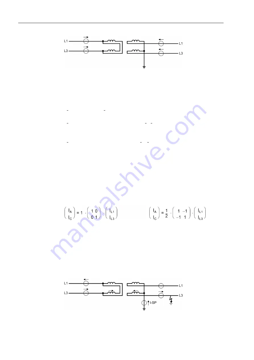
Figure 2-34
Example of a single-phase transformer with current definition
Like with three-phase power transformers, the currents are matched by programmed
coefficient matrices which simulate the difference currents in the transformer wind-
ings. The common form of these equations is:
Since the phase displacement between the windings can only be 0
°
or 180
°
, matching
is relevant only with respect to the treatment of the zero sequence current (besides
magnitude matching). If a „Starpoint“ of the protected transformer winding is not
earthed (left in figure 2-34), the phase currents can directly be used.
If the „starpoint“ is earthed (figure 2-34 right side), the zero sequence current must be
eliminated unless it can be compensated by considering the „starpoint current“. By
eliminating the zero sequence current, fault currents which flow through the transform-
er during earth faults in the network in case of an earth point in the protected zone
(transformer starpoint) are rendered harmless without any special external measures.
The matrices for the left and the right winding as per figure 2-34 are:
The disadvantage of elimination of the zero sequence current is that the differential
protection becomes less sensitive (by factor
1
/
2
because the zero sequence current
amounts to
1
/
2
in case of an earth faults in the protected zone). Higher earth fault sen-
sitivity can be achieved if the „starpoint“ current is available, i.e. if a CT is installed in
the „starpoint“ connection to earth and this current is fed to the device (figure 2-35).
For consideration of the earth fault current, the advanced parameter diff protection
with measured earth current, side x must be switched on (addresses
1211
DIFFw.IE1-MEAS
to
1215
DIFFw.IE5-MEAS
=
YES
).
Figure 2-35
Example of an earth fault outside a single-phase transformer with current distri-
bution
(
I
m
)
= k· (K)· (
I
n
)
with
(
I
m
)
- matrix of the matched currents
I
A
,
I
C
,
k
- constant factor for magnitude matching,
(K) -
coefficient
matrix,
(
I
n
)
- matrix of the phase currents
I
L1
,
I
L3
.
Содержание SIPROTEC 7UT613 series
Страница 16: ...Contents 16 7UT613 63x Manual C53000 G1176 C160 2 Literature 631 Glossary 623 Index 633 ...
Страница 30: ...1 Introduction 30 7UT613 63x Manual C53000 G1176 C160 2 ...
Страница 506: ...A Appendix 506 7UT613 63x Manual C53000 G1176 C160 2 7UT633 D E ...
Страница 508: ...A Appendix 508 7UT613 63x Manual C53000 G1176 C160 2 7UT633 P Q ...
Страница 510: ...A Appendix 510 7UT613 63x Manual C53000 G1176 C160 2 7UT635 D E ...
Страница 512: ...A Appendix 512 7UT613 63x Manual C53000 G1176 C160 2 7UT635 P Q ...
Страница 515: ...A 2 Terminal Assignments 515 7UT613 63x Manual C53000 G1176 C160 2 7UT633 B ...
Страница 516: ...A Appendix 516 7UT613 63x Manual C53000 G1176 C160 2 7UT633 B Figure A 7 General diagram 7UT633 panel surface mounting ...
Страница 517: ...A 2 Terminal Assignments 517 7UT613 63x Manual C53000 G1176 C160 2 7UT633 N ...
Страница 518: ...A Appendix 518 7UT613 63x Manual C53000 G1176 C160 2 7UT633 N Figure A 8 General diagram 7UT633 panel surface mounting ...
Страница 519: ...A 2 Terminal Assignments 519 7UT613 63x Manual C53000 G1176 C160 2 7UT635 B ...
Страница 520: ...A Appendix 520 7UT613 63x Manual C53000 G1176 C160 2 7UT635 B Figure A 9 General diagram 7UT635 panel surface mounting ...
Страница 521: ...A 2 Terminal Assignments 521 7UT613 63x Manual C53000 G1176 C160 2 7UT635 N ...
Страница 522: ...A Appendix 522 7UT613 63x Manual C53000 G1176 C160 2 7UT635 N Figure A 10 General diagram 7UT635 panel surface mounting ...
Страница 622: ...A Appendix 622 7UT613 63x Manual C53000 G1176 C160 2 ...
Страница 632: ...Literature 632 7UT613 63x Manual C53000 G1176 C160 2 ...


