


2.19 Monitoring Functions
281
7UT613/63x Manual
C53000-G1176-C160-2
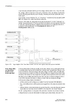
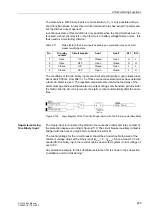
Figure 2-114
Current Symmetry Monitoring
Voltage Symmetry
In healthy network operation it can be expected that the voltages are nearly balanced.
If measured voltages are connected to the device, this symmetry is checked in the
device by magnitude comparison. To do this, the phase-to-earth voltages are mea-
sured. The lowest phase-to-earth voltage is set in relation to the highest. An imbalance
is detected when
|U
min
|/|U
max
| <
BAL. FACTOR U
as long as |U
max
| >
BALANCE U-LIMIT
TherebyU
max
is the largest of the three phase-to-phase voltages and U
min
the smallest.
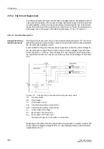
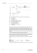
The symmetry factor
BAL. FACTOR U
is the measure for the asymmetry of the con-
ductor voltages; the limit value
BALANCE U-LIMIT
is the lower limit of the operating
range of this monitoring (see Figure Voltage Symmetry Monitoring). Both parameters
can be set. The dropout ratio is about 95 %.
This malfunction is reported as
„Fail U balance“
.
Figure 2-115
Voltage Symmetry Monitoring
Содержание SIPROTEC 7UT613 series
Страница 16: ...Contents 16 7UT613 63x Manual C53000 G1176 C160 2 Literature 631 Glossary 623 Index 633 ...
Страница 30: ...1 Introduction 30 7UT613 63x Manual C53000 G1176 C160 2 ...
Страница 506: ...A Appendix 506 7UT613 63x Manual C53000 G1176 C160 2 7UT633 D E ...
Страница 508: ...A Appendix 508 7UT613 63x Manual C53000 G1176 C160 2 7UT633 P Q ...
Страница 510: ...A Appendix 510 7UT613 63x Manual C53000 G1176 C160 2 7UT635 D E ...
Страница 512: ...A Appendix 512 7UT613 63x Manual C53000 G1176 C160 2 7UT635 P Q ...
Страница 515: ...A 2 Terminal Assignments 515 7UT613 63x Manual C53000 G1176 C160 2 7UT633 B ...
Страница 516: ...A Appendix 516 7UT613 63x Manual C53000 G1176 C160 2 7UT633 B Figure A 7 General diagram 7UT633 panel surface mounting ...
Страница 517: ...A 2 Terminal Assignments 517 7UT613 63x Manual C53000 G1176 C160 2 7UT633 N ...
Страница 518: ...A Appendix 518 7UT613 63x Manual C53000 G1176 C160 2 7UT633 N Figure A 8 General diagram 7UT633 panel surface mounting ...
Страница 519: ...A 2 Terminal Assignments 519 7UT613 63x Manual C53000 G1176 C160 2 7UT635 B ...
Страница 520: ...A Appendix 520 7UT613 63x Manual C53000 G1176 C160 2 7UT635 B Figure A 9 General diagram 7UT635 panel surface mounting ...
Страница 521: ...A 2 Terminal Assignments 521 7UT613 63x Manual C53000 G1176 C160 2 7UT635 N ...
Страница 522: ...A Appendix 522 7UT613 63x Manual C53000 G1176 C160 2 7UT635 N Figure A 10 General diagram 7UT635 panel surface mounting ...
Страница 622: ...A Appendix 622 7UT613 63x Manual C53000 G1176 C160 2 ...
Страница 632: ...Literature 632 7UT613 63x Manual C53000 G1176 C160 2 ...


