


2.1 General
65
7UT613/63x Manual
C53000-G1176-C160-2
As different connections are possible, you must now specify in the device how the con-
nected 1-phase voltage should be interpreted. This is done at address
263
VT U4
TYPE
. Set
Udelta transf.
if the voltage assigned acc. to address
262
is a dis-
placement voltage. It can also be any phase-to-earth voltage (e.g.
UL1E
transform.
), or a phase-to-phase voltage (e.g.
UL12 transform.
). If U4 is con-
nected to a voltage which is assigned to no side or measuring location, set
Ux
transformer
.
2.1.4.2
General Power System Data (Power System Data 1)
General
The device requires some plant and power system data in order to be able to adapt its
functions accordingly, dependent on the actual application. The data required include
for instance rated data of the substation and the measuring transformers, polarity and
connection of the measured quantities, if necessary features of the circuit breakers,
and others. There are also certain parameters common to all functions, i.e. not asso-
ciated with a specific protection, control or monitoring function. These data can only
be changed from a PC running DIGSI and are discussed in this section.
Rated Frequency
The rated frequency of the power system is set under address
270
Rated
Frequency
. The available rated frequencies are
50 Hz
,
60 Hz
and
16,7 Hz
.
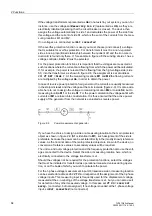
Phase Sequence
Under address
271
PHASE SEQ.
the presetting for clockwise rotation
L1 L2 L3
can
be changed if a power plant has an anticlockwise rotation
L1 L3 L2
. The phase se-
quence has no influence on the vector group conversion of the differential protection
as long as the identical phase rotation is present on all sides of the protected object.
This setting is irrelevant for single-phase application and is not accessible.
Figure 2-10
Phase rotation
Temperature Unit
The temperature of the hot-spot temperature calculation can be displayed in
Celsius
or
Fahrenheit
. This applies in particular for the output of the hot-spot temperature if
you are using the overload protection with hot-spot calculation. Set the desired tem-
perature unit in address
276
TEMP. UNIT
. Changing temperature units does not
mean that setting values which are linked to these temperature units will automatically
be converted. They have to be re-entered into their corresponding valid addresses.
Object Data with
Transformers
Transformer data are required if the device is used for differential protection for trans-
formers, i.e. if the following was set with the configuration of the protection functions
(functional scope) under address
105
PROT. OBJECT
=
3 phase transf.
or
1
phase transf.
or
Autotr. node
. In cases other than that, these settings are not
available.
Содержание SIPROTEC 7UT613 series
Страница 16: ...Contents 16 7UT613 63x Manual C53000 G1176 C160 2 Literature 631 Glossary 623 Index 633 ...
Страница 30: ...1 Introduction 30 7UT613 63x Manual C53000 G1176 C160 2 ...
Страница 506: ...A Appendix 506 7UT613 63x Manual C53000 G1176 C160 2 7UT633 D E ...
Страница 508: ...A Appendix 508 7UT613 63x Manual C53000 G1176 C160 2 7UT633 P Q ...
Страница 510: ...A Appendix 510 7UT613 63x Manual C53000 G1176 C160 2 7UT635 D E ...
Страница 512: ...A Appendix 512 7UT613 63x Manual C53000 G1176 C160 2 7UT635 P Q ...
Страница 515: ...A 2 Terminal Assignments 515 7UT613 63x Manual C53000 G1176 C160 2 7UT633 B ...
Страница 516: ...A Appendix 516 7UT613 63x Manual C53000 G1176 C160 2 7UT633 B Figure A 7 General diagram 7UT633 panel surface mounting ...
Страница 517: ...A 2 Terminal Assignments 517 7UT613 63x Manual C53000 G1176 C160 2 7UT633 N ...
Страница 518: ...A Appendix 518 7UT613 63x Manual C53000 G1176 C160 2 7UT633 N Figure A 8 General diagram 7UT633 panel surface mounting ...
Страница 519: ...A 2 Terminal Assignments 519 7UT613 63x Manual C53000 G1176 C160 2 7UT635 B ...
Страница 520: ...A Appendix 520 7UT613 63x Manual C53000 G1176 C160 2 7UT635 B Figure A 9 General diagram 7UT635 panel surface mounting ...
Страница 521: ...A 2 Terminal Assignments 521 7UT613 63x Manual C53000 G1176 C160 2 7UT635 N ...
Страница 522: ...A Appendix 522 7UT613 63x Manual C53000 G1176 C160 2 7UT635 N Figure A 10 General diagram 7UT635 panel surface mounting ...
Страница 622: ...A Appendix 622 7UT613 63x Manual C53000 G1176 C160 2 ...
Страница 632: ...Literature 632 7UT613 63x Manual C53000 G1176 C160 2 ...


