


2.1 General
81
7UT613/63x Manual
C53000-G1176-C160-2
As the above examples show, the protection function can be assigned as desired.
Generally speaking:
• Where a 3-phase protection function is assigned to a measuring location, the cur-
rents are acquired at this location, regardless of whether it is assigned to the main
protected object or not.
• Where a 3-phase protection function is assigned to a side (of the main protected
object), the sum of the currents flowing in at this side from the measuring locations
assigned to it is acquired (for each phase).
• Please note also that the earth overcurrent protection will receive from the auxiliary
measuring location assigned here not only its measured value, but also circuit
breaker information (current flow and manual-close detection).
The same basic principles apply to the two additional overcurrent protection functions.
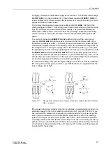
With reference to the example in figure 2-2, the first overcurrent protection can be de-
termined as reserve protection at the high-voltage side by setting address
420
DMT/IDMT Ph AT
=
Side 1
(as above), the second overcurrent protection as protec-
tion of the station's own requirement feeder (address
430
DMT/IDMT Ph2 AT
=
Measuring loc.3
) and the third overcurrent protection as protection of the cable
feeder (address
432
DMT/IDMT Ph3 AT
=
Measuring loc.5
).
The same applies also to the assignment of the overcurrent protection for zero se-
quence current (section 2.4.1) in address
422
DMT/IDMT 3I0 AT
. Please keep in
mind that this protection function acquires the sum of the phase currents and is there-
fore considered as a three-phase protection function. The assignment, however, can
differ from the assignment used by the overcurrent protection for phase currents. This
means that in the example shown in figure 2-2, the overcurrent protection can be
easily used for phase currents (
DMT/IDMT Ph AT
) at the higher voltage side of the
transformer (
Side 1
), and the overcurrent protection for residual currents (
DMT/IDMT
3I0 AT
) at the lower voltage side (
Measuring loc.4
).
The two additional protection functions in addresses
434
DMT/IDMT3I0-2AT
can
also be assigned to the second residual current overcurrent protection and address
436
DMT/IDMT3I0-3AT
to the third residual overcurrent protection.
The same options exist for the unbalanced load protection (address
440
UNBAL.
LOAD AT
, section 2.8), which can also be used at a side of the main protection object
or at any - assigned or non-assigned - 3-phase measuring location.
The overload protection (section 2.9) always refers to one side of the main protected
object. Consequently, address
442
THERM. O/L AT
allows to select only a side, not
a measuring location.
Since the cause for overload comes from outside of the protected object, the overload
current is a traversing current. Therefore it does not necessarily have to be detected
at the infeeding side.
• For transformers with tap changer the overload protection is assigned to the non-
regulated side as it is the only side where we have a defined relation between rated
current and rated power.
• For generators, the overload protection is usually on the starpoint side.
• For motors and shunt reactors, the overload protection is connected to the current
transformers of the feeding side.
• For series reactors or short cables, any side can be selected.
• For busbar sections or overhead lines, the overload protection is, generally, not
used since climate and weather conditions (air temperature, wind) change too
quickly and it is therefore not reasonable to calculate the temperature rise. In this
case, however, a current-dependent alarm stage is able to warn of an imminent
overload.
Содержание SIPROTEC 7UT613 series
Страница 16: ...Contents 16 7UT613 63x Manual C53000 G1176 C160 2 Literature 631 Glossary 623 Index 633 ...
Страница 30: ...1 Introduction 30 7UT613 63x Manual C53000 G1176 C160 2 ...
Страница 506: ...A Appendix 506 7UT613 63x Manual C53000 G1176 C160 2 7UT633 D E ...
Страница 508: ...A Appendix 508 7UT613 63x Manual C53000 G1176 C160 2 7UT633 P Q ...
Страница 510: ...A Appendix 510 7UT613 63x Manual C53000 G1176 C160 2 7UT635 D E ...
Страница 512: ...A Appendix 512 7UT613 63x Manual C53000 G1176 C160 2 7UT635 P Q ...
Страница 515: ...A 2 Terminal Assignments 515 7UT613 63x Manual C53000 G1176 C160 2 7UT633 B ...
Страница 516: ...A Appendix 516 7UT613 63x Manual C53000 G1176 C160 2 7UT633 B Figure A 7 General diagram 7UT633 panel surface mounting ...
Страница 517: ...A 2 Terminal Assignments 517 7UT613 63x Manual C53000 G1176 C160 2 7UT633 N ...
Страница 518: ...A Appendix 518 7UT613 63x Manual C53000 G1176 C160 2 7UT633 N Figure A 8 General diagram 7UT633 panel surface mounting ...
Страница 519: ...A 2 Terminal Assignments 519 7UT613 63x Manual C53000 G1176 C160 2 7UT635 B ...
Страница 520: ...A Appendix 520 7UT613 63x Manual C53000 G1176 C160 2 7UT635 B Figure A 9 General diagram 7UT635 panel surface mounting ...
Страница 521: ...A 2 Terminal Assignments 521 7UT613 63x Manual C53000 G1176 C160 2 7UT635 N ...
Страница 522: ...A Appendix 522 7UT613 63x Manual C53000 G1176 C160 2 7UT635 N Figure A 10 General diagram 7UT635 panel surface mounting ...
Страница 622: ...A Appendix 622 7UT613 63x Manual C53000 G1176 C160 2 ...
Страница 632: ...Literature 632 7UT613 63x Manual C53000 G1176 C160 2 ...


