


2.5 Time Overcurrent Protection for Earth Current
183
7UT613/63x Manual
C53000-G1176-C160-2
User-defined Char-
acteristics
When user-defined curves are utilised, the tripping curve may be defined point by
point. Up to 20 pairs of values (current, time) may be entered. The device then approx-
imates the characteristics by linear interpolation.
If required, the dropout characteristic can also be defined (see function description for
„Dropout“. If no user-configurable dropout characteristic is desired, dropout is initiated
when approx. a 95 % of the pickup value is undershot; when a new pickup is evoked,
the timer starts again at zero.
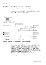
2.5.4
Manual Close Command
When a circuit breaker is closed onto a faulted protective object, a high speed re-trip
by the breaker is often desired. The manual closing feature is designed to remove the
delay from one of the time overcurrent stages when the breaker is manually closed
onto a fault. The time delay is then bypassed via an impulse from the external control
switch. This pulse is prolonged by at least 300 ms. To enable the device to react prop-
erly on occurrence of a fault, address
2408
A
IE MAN. CLOSE
have to be set accord-
ingly.
Processing of the manual close command can be executed for each measuring loca-
tion or side. Manual close signal is also generated when an internal control command
is given to a breaker which is assigned to the same protection function as the time
earth overcurrent protection, in the Power System Data 1 (subsection 2.1.4).
Strict attention must be paid that the manual close condition is derived from
that
circuit
breaker which feeds the object that is protected by the earth overcurrent protection!
2.5.5
Dynamic Cold Load Pickup
Dynamic changeover of pickup values is available also for time overcurrent protection
for earth current as it is for the time overcurrent protection for phase currents and zero
sequence current. Processing of the dynamic cold load pickup conditions is the same
for all time overcurrent stages, and is explained in Section 2.6.
The alternative values themselves are individually set for each of the stages.
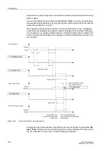
2.5.6
Inrush Restraint
Earth current time overcurrent protection provides an integrated inrush restraint func-
tion which blocks the overcurrent stages
If the second harmonic content of the earth current exceeds a selectable threshold,
tripping is blocked.
The inrush stabilisation has an upper limit: If a certain (adjustable) current value is ex-
ceeded, it will not be effective any more, since it must then be an internal current-in-
tensive short-circuit. The lower limit is the operating limit of the harmonic filter (0.1
I
N
).
Содержание SIPROTEC 7UT613 series
Страница 16: ...Contents 16 7UT613 63x Manual C53000 G1176 C160 2 Literature 631 Glossary 623 Index 633 ...
Страница 30: ...1 Introduction 30 7UT613 63x Manual C53000 G1176 C160 2 ...
Страница 506: ...A Appendix 506 7UT613 63x Manual C53000 G1176 C160 2 7UT633 D E ...
Страница 508: ...A Appendix 508 7UT613 63x Manual C53000 G1176 C160 2 7UT633 P Q ...
Страница 510: ...A Appendix 510 7UT613 63x Manual C53000 G1176 C160 2 7UT635 D E ...
Страница 512: ...A Appendix 512 7UT613 63x Manual C53000 G1176 C160 2 7UT635 P Q ...
Страница 515: ...A 2 Terminal Assignments 515 7UT613 63x Manual C53000 G1176 C160 2 7UT633 B ...
Страница 516: ...A Appendix 516 7UT613 63x Manual C53000 G1176 C160 2 7UT633 B Figure A 7 General diagram 7UT633 panel surface mounting ...
Страница 517: ...A 2 Terminal Assignments 517 7UT613 63x Manual C53000 G1176 C160 2 7UT633 N ...
Страница 518: ...A Appendix 518 7UT613 63x Manual C53000 G1176 C160 2 7UT633 N Figure A 8 General diagram 7UT633 panel surface mounting ...
Страница 519: ...A 2 Terminal Assignments 519 7UT613 63x Manual C53000 G1176 C160 2 7UT635 B ...
Страница 520: ...A Appendix 520 7UT613 63x Manual C53000 G1176 C160 2 7UT635 B Figure A 9 General diagram 7UT635 panel surface mounting ...
Страница 521: ...A 2 Terminal Assignments 521 7UT613 63x Manual C53000 G1176 C160 2 7UT635 N ...
Страница 522: ...A Appendix 522 7UT613 63x Manual C53000 G1176 C160 2 7UT635 N Figure A 10 General diagram 7UT635 panel surface mounting ...
Страница 622: ...A Appendix 622 7UT613 63x Manual C53000 G1176 C160 2 ...
Страница 632: ...Literature 632 7UT613 63x Manual C53000 G1176 C160 2 ...