


2.14 Undervoltage Protection
257
7UT613/63x Manual
C53000-G1176-C160-2
The respective delay time
T U<
(address
5213
) is supposed to bridge the permissible
short-term voltage dips during continuous undervoltage, which may lead to an unsta-
ble operation, however, it is supposed to be switched off within a few seconds.
For the U<< stage, a lower pickup threshold with a short delay should be set so that
in case of heavy voltage dips a quick trip can occur, e.g. 65 % of the nominal voltage
with 0.5 s delay.
If the undervoltage protection is assigned to one side of the main protected object or
the three-phase busbar, the pickup value must be set as reference value under
address
5215
U<<
, e.g. 0.65. When assigned to a measuring location, the value of
phase-phase voltage must be set under address
5214
U<<
in Volt, e.g. 71.5. V at
U
N sec
= 110 V (65 % of 110 V).
The set times are additional time delays that do not include the operating time (mea-
suring time, dropout time) of the protection function. If a delay time is set to
∞
, this
does not result in a trip, however, the pickup will be indicated.
Dropout Ratio
The drop-out ratio can be adjusted to the operating conditions at address
5217
DOUT
RATIO
. This parameter can only be altered in DIGSI at
Additional Settings
.
2.14.3 Settings
Addresses which have an appended "A" can only be changed with DIGSI, under Ad-
ditional Settings.
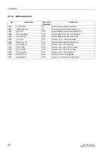
2.14.4 Information List
Addr.
Parameter
Setting Options
Default Setting
Comments
5201
UNDERVOLTAGE
OFF
ON
Block relay
OFF
Undervoltage Protection
5211
U<
10.0 .. 125.0 V
75.0 V
U< Pickup
5212
U<
0.10 .. 1.25 U/UnS
0.75 U/UnS
Pick-up voltage U<
5213
T U<
0.00 .. 60.00 sec;
∞
3.00 sec
T U< Time Delay
5214
U<<
10.0 .. 125.0 V
65.0 V
U<< Pickup
5215
U<<
0.10 .. 1.25 U/UnS
0.65 U/UnS
Pick-up voltage U<<
5216
T U<<
0.00 .. 60.00 sec;
∞
0.50 sec
T U<< Time Delay
5217A
DOUT RATIO
1.01 .. 1.20
1.05
U<, U<< Drop Out Ratio
No.
Information
Type of In-
formation
Comments
033.2404 >BLOCK U/V
SP
>BLOCK undervoltage protection
033.2411
Undervolt. OFF
OUT
Undervoltage protection is switched OFF
033.2412 Undervolt. BLK
OUT
Undervoltage protection is BLOCKED
033.2413 Undervolt. ACT
OUT
Undervoltage protection is ACTIVE
033.2491 U< err. Obj.
OUT
Undervoltage: Not avail. for this obj.
033.2492 U< err. VT
OUT
Undervoltage: error assigned VT
Содержание SIPROTEC 7UT613 series
Страница 16: ...Contents 16 7UT613 63x Manual C53000 G1176 C160 2 Literature 631 Glossary 623 Index 633 ...
Страница 30: ...1 Introduction 30 7UT613 63x Manual C53000 G1176 C160 2 ...
Страница 506: ...A Appendix 506 7UT613 63x Manual C53000 G1176 C160 2 7UT633 D E ...
Страница 508: ...A Appendix 508 7UT613 63x Manual C53000 G1176 C160 2 7UT633 P Q ...
Страница 510: ...A Appendix 510 7UT613 63x Manual C53000 G1176 C160 2 7UT635 D E ...
Страница 512: ...A Appendix 512 7UT613 63x Manual C53000 G1176 C160 2 7UT635 P Q ...
Страница 515: ...A 2 Terminal Assignments 515 7UT613 63x Manual C53000 G1176 C160 2 7UT633 B ...
Страница 516: ...A Appendix 516 7UT613 63x Manual C53000 G1176 C160 2 7UT633 B Figure A 7 General diagram 7UT633 panel surface mounting ...
Страница 517: ...A 2 Terminal Assignments 517 7UT613 63x Manual C53000 G1176 C160 2 7UT633 N ...
Страница 518: ...A Appendix 518 7UT613 63x Manual C53000 G1176 C160 2 7UT633 N Figure A 8 General diagram 7UT633 panel surface mounting ...
Страница 519: ...A 2 Terminal Assignments 519 7UT613 63x Manual C53000 G1176 C160 2 7UT635 B ...
Страница 520: ...A Appendix 520 7UT613 63x Manual C53000 G1176 C160 2 7UT635 B Figure A 9 General diagram 7UT635 panel surface mounting ...
Страница 521: ...A 2 Terminal Assignments 521 7UT613 63x Manual C53000 G1176 C160 2 7UT635 N ...
Страница 522: ...A Appendix 522 7UT613 63x Manual C53000 G1176 C160 2 7UT635 N Figure A 10 General diagram 7UT635 panel surface mounting ...
Страница 622: ...A Appendix 622 7UT613 63x Manual C53000 G1176 C160 2 ...
Страница 632: ...Literature 632 7UT613 63x Manual C53000 G1176 C160 2 ...


