


2.9 Thermal Overload Protection
229
7UT613/63x Manual
C53000-G1176-C160-2
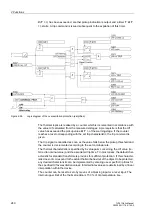
that corresponds with the setting in accordance with the functional scope (section
2.1.3.1) under address
191
RTD CONNECTION
.
The characteristic values of the temperature detectors are set separately, see section
RTD-boxes 2.10).
Hot-Spot Stages
There are two annunciation stages for hot-spot temperature. To set a specific hot-spot
temperature value (expressed in
°
C), which is meant to generate the warning signal
(stage 1), use address
4222
HOT SPOT ST. 1
. Use address
4224
HOT SPOT ST.
2
to indicate the corresponding alarm temperature (stage 2). It can also be used for
the tripping of circuit breakers if the outgoing message (No 1542) is allocated to a trip
relay.
If address
276
TEMP. UNIT
is set to degree Fahrenheit during configuration of the
Power System Data 1
, thresholds for warning and alarm temperatures have to be
expressed in Fahrenheit at addresses
4223
and
4225
.
If the temperature unit is changed in address
276
, after having set the thresholds for
temperature, these thresholds changed for the temperature unit, must be reset in the
respective addresses.
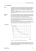
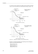
Ageing Rate
For ageing rate L thresholds can also be set, i.e. for the warning signal (Stage 1) in
address
4226
AG. RATE ST. 1
and for alarm signal (Stage 2) in address
4227
AG.
RATE ST. 2
. This information is referred to the relative ageing, i.e. L=1 is reached at
98
°
C or 208
°
F at the hot spot. L > 1 refers to an accelerated ageing, L < 1 to delayed
ageing.
Cooling Method
and Insulation Data
Set in address
4231
METH.COOLING
which cooling method is used:
ON
=
O
il
N
atural
for natural cooling,
OF
=
O
il
F
orced for oil forced cooling or
OD
=
O
il
D
irected for oil di-
rected cooling. The definitions under margin heading „Cooling Methods“ in the func-
tion description of the hot-spot calculation.
For hot-spot calculation, the device requires winding exponent Y and the hot-spot to
top-oil gradient H
gr
, that can be set under
4232
Y-WIND.EXPONENT
and
4233
HOT-
SPOT GR
. If the corresponding information is not available, it can be taken from the
IEC 60354. An extract from the corresponding table of the standard with the technical
data relevant for this project can be found hereinafter.
Table 2-9
Thermal characteristics of power transformers
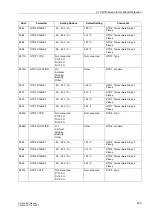
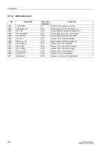
Additional Thermal
Overload Protec-
tion Function
In the aforementioned description, the first thermal overload protection is described re-
spectively. The differences in the parameter addresses and message numbers of the
first and second thermal overload protection are illustrated in the following table. The
positions marked by x are identical.
Cooling method:
Distribution
transformers
Medium and large power
transformers
ONAN
ON..
OF..
OD..
Winding exponent
Y
1.6
1.8
1.8
2.0
Insulation temperature gradient
H
gr
23
26
22
29
Parameter addresses
Message no.
1. thermal overload protection function
42xx
044.xxxx(.01)
2. thermal overload protection function
44xx
204.xxxx(.01)
Содержание SIPROTEC 7UT613 series
Страница 16: ...Contents 16 7UT613 63x Manual C53000 G1176 C160 2 Literature 631 Glossary 623 Index 633 ...
Страница 30: ...1 Introduction 30 7UT613 63x Manual C53000 G1176 C160 2 ...
Страница 506: ...A Appendix 506 7UT613 63x Manual C53000 G1176 C160 2 7UT633 D E ...
Страница 508: ...A Appendix 508 7UT613 63x Manual C53000 G1176 C160 2 7UT633 P Q ...
Страница 510: ...A Appendix 510 7UT613 63x Manual C53000 G1176 C160 2 7UT635 D E ...
Страница 512: ...A Appendix 512 7UT613 63x Manual C53000 G1176 C160 2 7UT635 P Q ...
Страница 515: ...A 2 Terminal Assignments 515 7UT613 63x Manual C53000 G1176 C160 2 7UT633 B ...
Страница 516: ...A Appendix 516 7UT613 63x Manual C53000 G1176 C160 2 7UT633 B Figure A 7 General diagram 7UT633 panel surface mounting ...
Страница 517: ...A 2 Terminal Assignments 517 7UT613 63x Manual C53000 G1176 C160 2 7UT633 N ...
Страница 518: ...A Appendix 518 7UT613 63x Manual C53000 G1176 C160 2 7UT633 N Figure A 8 General diagram 7UT633 panel surface mounting ...
Страница 519: ...A 2 Terminal Assignments 519 7UT613 63x Manual C53000 G1176 C160 2 7UT635 B ...
Страница 520: ...A Appendix 520 7UT613 63x Manual C53000 G1176 C160 2 7UT635 B Figure A 9 General diagram 7UT635 panel surface mounting ...
Страница 521: ...A 2 Terminal Assignments 521 7UT613 63x Manual C53000 G1176 C160 2 7UT635 N ...
Страница 522: ...A Appendix 522 7UT613 63x Manual C53000 G1176 C160 2 7UT635 N Figure A 10 General diagram 7UT635 panel surface mounting ...
Страница 622: ...A Appendix 622 7UT613 63x Manual C53000 G1176 C160 2 ...
Страница 632: ...Literature 632 7UT613 63x Manual C53000 G1176 C160 2 ...


