


2.1 General
53
7UT613/63x Manual
C53000-G1176-C160-2
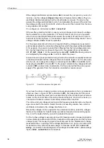
Figure 2-5
Topology of an auto-transformer with a compensation winding which is used as
tertiary winding
Sides:
S1
High voltage side of the main protected object (auto-transformer)
S2
Low voltage side of the main protected object (auto-transformer)
S3
Tertiary winding side (accessible compensation winding) of the main protected object
Measuring locations 3-phase, assigned:
M1
Measuring location, assigned to the main protected object, side 1
M2
Measuring location, assigned to the main protected object, side 1
M3
Measuring location, assigned to the main protected object, side 2
M4
Measuring location, assigned to the main protected object, side 3
A further tap of the winding can also be used as the third side. Be aware that the num-
bering sequence always starts with the auto-connected winding: full winding, taps, and
then accessible delta winding if required.
Auto-Transformer
Banks
If three single-phase auto-transformers are arranged as a power transformer bank, the
connections of the starpoint leads of the auto-windings are accessible and often pro-
vided with current transformers. During configuration of the functional scope in section
2.1.3 you have decided whether a differential protection must be realised via the entire
transformer bank, or whether you prefer a current comparison via the winding of each
phase by means of current law.
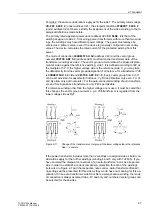
Differential protection over the entire power transformer bank:
Regarding the first case, figure 2-6 gives an example of a 3-phase presentation. In this
example we have
3
sides and
3
assigned three-phase measuring locations. The auto-
connected winding terminals form the sides
S1
(full winding) and
S2
(tap) with the as-
signed 3-phase measuring locations
M1
and
M2
. As the delta winding functions both
as the tertiary winding and the compensation winding, it is the third side
S3
with mea-
suring location
M3
.
The currents measured in the starpoint connections are not immediately required.
However, you can assign it to a further three-phase measuring location. The device
then calculates the current sum as earth current, if this had been set accordingly in the
differential protection (see section 2.2.7).
Содержание SIPROTEC 7UT613 series
Страница 16: ...Contents 16 7UT613 63x Manual C53000 G1176 C160 2 Literature 631 Glossary 623 Index 633 ...
Страница 30: ...1 Introduction 30 7UT613 63x Manual C53000 G1176 C160 2 ...
Страница 506: ...A Appendix 506 7UT613 63x Manual C53000 G1176 C160 2 7UT633 D E ...
Страница 508: ...A Appendix 508 7UT613 63x Manual C53000 G1176 C160 2 7UT633 P Q ...
Страница 510: ...A Appendix 510 7UT613 63x Manual C53000 G1176 C160 2 7UT635 D E ...
Страница 512: ...A Appendix 512 7UT613 63x Manual C53000 G1176 C160 2 7UT635 P Q ...
Страница 515: ...A 2 Terminal Assignments 515 7UT613 63x Manual C53000 G1176 C160 2 7UT633 B ...
Страница 516: ...A Appendix 516 7UT613 63x Manual C53000 G1176 C160 2 7UT633 B Figure A 7 General diagram 7UT633 panel surface mounting ...
Страница 517: ...A 2 Terminal Assignments 517 7UT613 63x Manual C53000 G1176 C160 2 7UT633 N ...
Страница 518: ...A Appendix 518 7UT613 63x Manual C53000 G1176 C160 2 7UT633 N Figure A 8 General diagram 7UT633 panel surface mounting ...
Страница 519: ...A 2 Terminal Assignments 519 7UT613 63x Manual C53000 G1176 C160 2 7UT635 B ...
Страница 520: ...A Appendix 520 7UT613 63x Manual C53000 G1176 C160 2 7UT635 B Figure A 9 General diagram 7UT635 panel surface mounting ...
Страница 521: ...A 2 Terminal Assignments 521 7UT613 63x Manual C53000 G1176 C160 2 7UT635 N ...
Страница 522: ...A Appendix 522 7UT613 63x Manual C53000 G1176 C160 2 7UT635 N Figure A 10 General diagram 7UT635 panel surface mounting ...
Страница 622: ...A Appendix 622 7UT613 63x Manual C53000 G1176 C160 2 ...
Страница 632: ...Literature 632 7UT613 63x Manual C53000 G1176 C160 2 ...