


2 Functions
174
7UT613/63x Manual
C53000-G1176-C160-2
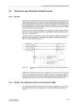
Inverse Time Over-
current Stage3I0p
with IEC Character-
istics
The inverse time stage, depending on the configuration of the functional scope,
address
122
(see 2.1.3.1), enables the user to select different characteristics.
With the IEC characteristics (address
122
DMT/IDMT 3I0
=
TOC IEC
) the following
options are available at address
2226
IEC CURVE
:
•
Normal Inverse
(inverse, type A according to IEC 60255-3),
•
Very Inverse
(very inverse, type B according to IEC 60255-3),
•
Extremely Inv.
(extremely inverse, type C according to IEC 60255-3), and
•
Long Inverse
(longtime, type B according to IEC 60255-3).
The characteristics and the equations on which they are based, are listed in the „Tech-
nical Data“.
If the inverse time trip characteristic is selected, it must be noted that a safety factor
of about 1.1 has already been included between the pickup value and the setting
value. This means that a pickup will only occur if a current of about 1.1 times the
setting value is present.
The current value is set under address
2221
or
2222
3I0p
. The most relevant for this
setting is the minimum appearing earth fault current. Please note that, in case of
various measuring locations, higher measuring tolerance may occur due to summa-
tion errors.
The corresponding time multiplier is accessible via address
2223
T 3I0p
. This has
to be coordinated with the grading coordination chart of the network. For earth cur-
rents with earthed network, you can mostly set up a separate grading coordination
chart with shorter delay times. If you set a very small pickup value, consider that the
inrush restraint function cannot operate below 10 % nominal current (lower limit of har-
monic filtering). An adequate time delay could be reasonable if inrush restraint is used.
The time multiplier can also be set to
∞
. If set to infinity, the pickup of this function will
be indicated but the stage will not trip after pickup. If the
I
p stage is not required at all,
select address
122
DMT/IDMT 3I0
=
Definite Time
when configuring the protec-
tion functions.
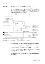
If under address
2225
TOC DROP-OUT
the
Disk Emulation
is set, dropout is pro-
duced according to the dropout characteristic, as described in subsection „Dropout
Behaviour“.
Inverse Time Over-
current Stage 3I0p
with ANSI Charac-
teristics
The inverse time stage, depending on the configuration of the functional scope,
address
122
(see 2.1.3.1), enables the user to select different characteristics.
With the ANSI characteristics (address
122
DMT/IDMT 3I0
=
TOC ANSI
) the follow-
ing is made available in address
2227
ANSI CURVE
:
•
Definite Inv.
,
•
Extremely Inv.
,
•
Inverse
,
•
Long Inverse
,
•
Moderately Inv.
,
•
Short Inverse
, and
•
Very Inverse
.
The characteristics and the formulas on which they are based, are listed in the „Tech-
nical Data“.
If the inverse time trip characteristic is selected, please note that a safety factor of
about 1.1 has already been included between the pickup value and the setting value.
Содержание SIPROTEC 7UT613 series
Страница 16: ...Contents 16 7UT613 63x Manual C53000 G1176 C160 2 Literature 631 Glossary 623 Index 633 ...
Страница 30: ...1 Introduction 30 7UT613 63x Manual C53000 G1176 C160 2 ...
Страница 506: ...A Appendix 506 7UT613 63x Manual C53000 G1176 C160 2 7UT633 D E ...
Страница 508: ...A Appendix 508 7UT613 63x Manual C53000 G1176 C160 2 7UT633 P Q ...
Страница 510: ...A Appendix 510 7UT613 63x Manual C53000 G1176 C160 2 7UT635 D E ...
Страница 512: ...A Appendix 512 7UT613 63x Manual C53000 G1176 C160 2 7UT635 P Q ...
Страница 515: ...A 2 Terminal Assignments 515 7UT613 63x Manual C53000 G1176 C160 2 7UT633 B ...
Страница 516: ...A Appendix 516 7UT613 63x Manual C53000 G1176 C160 2 7UT633 B Figure A 7 General diagram 7UT633 panel surface mounting ...
Страница 517: ...A 2 Terminal Assignments 517 7UT613 63x Manual C53000 G1176 C160 2 7UT633 N ...
Страница 518: ...A Appendix 518 7UT613 63x Manual C53000 G1176 C160 2 7UT633 N Figure A 8 General diagram 7UT633 panel surface mounting ...
Страница 519: ...A 2 Terminal Assignments 519 7UT613 63x Manual C53000 G1176 C160 2 7UT635 B ...
Страница 520: ...A Appendix 520 7UT613 63x Manual C53000 G1176 C160 2 7UT635 B Figure A 9 General diagram 7UT635 panel surface mounting ...
Страница 521: ...A 2 Terminal Assignments 521 7UT613 63x Manual C53000 G1176 C160 2 7UT635 N ...
Страница 522: ...A Appendix 522 7UT613 63x Manual C53000 G1176 C160 2 7UT635 N Figure A 10 General diagram 7UT635 panel surface mounting ...
Страница 622: ...A Appendix 622 7UT613 63x Manual C53000 G1176 C160 2 ...
Страница 632: ...Literature 632 7UT613 63x Manual C53000 G1176 C160 2 ...


