


2.19 Monitoring Functions
279
7UT613/63x Manual
C53000-G1176-C160-2
2.19
Monitoring Functions
The device incorporates comprehensive supervision functions which cover both hard-
ware and software; the measured values are continuously checked for plausibility, so
that the CT circuits are also included in the monitoring system to a large extent. It is
also possible to implement trip circuit supervision, using appropriate binary inputs as
available.
2.19.1 Measurement Supervision
2.19.1.1 Hardware Monitoring
The device is monitored by the measurement inputs and the output relays. Monitoring
circuits and the processor check the hardware for malfunctions and abnormal states.
Auxiliary and Refer-
ence Voltages
The processor voltage of 5 V is monitored by the hardware, as the processor cannot
operate if the voltage drops below the minimum value. In that case, the device is not
operational. When the correct voltage has re-established the processor system is re-
started.
Failure or switch-off of the supply voltage sets the device out of operation; this status
is signalled by a „life contact“ (closed or open). Transient dips in supply voltage do not
disturb the function of the device (see Technical Data).
The processor monitors the offset and the reference voltage of the AD (analogue-to-
digital converter). The protection is blocked in case of inadmissible deviations. Contin-
uous malfunctioning is indicated by the alarm
„Error MeasurSys“
, No 181.
Back-up Battery
The back-up battery guarantees that the internal clock continues to work and that
metered values and alarms are stored if the auxiliary voltage fails. The charge level of
the battery is checked regularly. On its undershooting a minimum admissible voltage,
the indication
„Fail Battery“
, No. 177 is issued.
Memory Compo-
nents
The working memory (RAM) is tested during booting of the system. If a malfunction
occurs, the starting sequence is interrupted and an LED blinks. During operation the
memories are checked with the help of their checksum.
For the program memory, the cross-check sum is cyclically generated and compared
to a stored reference program cross-check sum.
For the parameter memory, the cross-check sum is cyclically generated and com-
pared to the cross-check sum that is refreshed after each prarameterisation change.
If a fault occurs, the processor system is restarted.
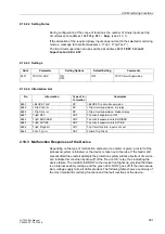
Sampling Frequen-
cy
The sampling frequency and the synchronism between the ADC s (analog-to-digital
converters) is continuously monitored. If deviations cannot be corrected by another
synchronisation, the device sets itself out of operation and the red LED „ERROR“
lights up. The readiness relay drops off and signals the malfunction by its „life contact“.
Содержание SIPROTEC 7UT613 series
Страница 16: ...Contents 16 7UT613 63x Manual C53000 G1176 C160 2 Literature 631 Glossary 623 Index 633 ...
Страница 30: ...1 Introduction 30 7UT613 63x Manual C53000 G1176 C160 2 ...
Страница 506: ...A Appendix 506 7UT613 63x Manual C53000 G1176 C160 2 7UT633 D E ...
Страница 508: ...A Appendix 508 7UT613 63x Manual C53000 G1176 C160 2 7UT633 P Q ...
Страница 510: ...A Appendix 510 7UT613 63x Manual C53000 G1176 C160 2 7UT635 D E ...
Страница 512: ...A Appendix 512 7UT613 63x Manual C53000 G1176 C160 2 7UT635 P Q ...
Страница 515: ...A 2 Terminal Assignments 515 7UT613 63x Manual C53000 G1176 C160 2 7UT633 B ...
Страница 516: ...A Appendix 516 7UT613 63x Manual C53000 G1176 C160 2 7UT633 B Figure A 7 General diagram 7UT633 panel surface mounting ...
Страница 517: ...A 2 Terminal Assignments 517 7UT613 63x Manual C53000 G1176 C160 2 7UT633 N ...
Страница 518: ...A Appendix 518 7UT613 63x Manual C53000 G1176 C160 2 7UT633 N Figure A 8 General diagram 7UT633 panel surface mounting ...
Страница 519: ...A 2 Terminal Assignments 519 7UT613 63x Manual C53000 G1176 C160 2 7UT635 B ...
Страница 520: ...A Appendix 520 7UT613 63x Manual C53000 G1176 C160 2 7UT635 B Figure A 9 General diagram 7UT635 panel surface mounting ...
Страница 521: ...A 2 Terminal Assignments 521 7UT613 63x Manual C53000 G1176 C160 2 7UT635 N ...
Страница 522: ...A Appendix 522 7UT613 63x Manual C53000 G1176 C160 2 7UT635 N Figure A 10 General diagram 7UT635 panel surface mounting ...
Страница 622: ...A Appendix 622 7UT613 63x Manual C53000 G1176 C160 2 ...
Страница 632: ...Literature 632 7UT613 63x Manual C53000 G1176 C160 2 ...


