


2.9 Thermal Overload Protection
227
7UT613/63x Manual
C53000-G1176-C160-2
tables. As the nominal data of the protected object and the current transformer ratios
are known to the device, the
K-FACTOR
can be set immediately.
When using the method with hot-spot calculation according to IEC 60354, setting
K-
FACTOR
= 1 is advisable as all remaining parameters refer to the rated current of the
assigned side of the protected object.
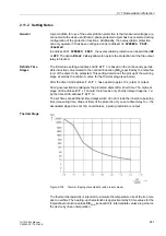
Time Constant
τ
for
Thermal Replica
The thermal time constant
τ
th
for the thermal replica is set under address
4203
TIME
CONSTANT
. This is also provided by the manufacturer.
Please note that the time constant is set in minutes. Quite often other values for de-
termining the time constant are stated which can be converted into the time constant
as follows:
1-s current
permissible current for application time other than 1 s, e.g. for 0.5 s
t6-time; this is the time in seconds for which a current of 6 times the rated current of
the protected object may flow
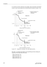
Calculation examples:
Cable with
permissible continuous current 322 A
permissible 1-s current 13.5 kA
Setting value
TIME CONSTANT
= 29.4 min
Motor with t6–time 12 s
Setting value
TIME CONSTANT
= 7.2 min
For rotating machines, the thermal time constant set under
TIME CONSTANT
is valid
for as long as the machine is running. The machine will cool down significantly slower
during stand-still or running down, if it is self-ventilated. This phenomenon is consid-
ered by a higher stand-still time constant
K
τ
-FACTOR
(address
4207
) which is set as
a factor of the normal time constant. This parameter can only be set with DIGSI under
Additional Settings
.
If it not necessary to distinguish between different time constants, e.g. with cables,
transformers, reactors, etc., retain the factor
K
τ
-FACTOR
=
1.0
(default setting).
Содержание SIPROTEC 7UT613 series
Страница 16: ...Contents 16 7UT613 63x Manual C53000 G1176 C160 2 Literature 631 Glossary 623 Index 633 ...
Страница 30: ...1 Introduction 30 7UT613 63x Manual C53000 G1176 C160 2 ...
Страница 506: ...A Appendix 506 7UT613 63x Manual C53000 G1176 C160 2 7UT633 D E ...
Страница 508: ...A Appendix 508 7UT613 63x Manual C53000 G1176 C160 2 7UT633 P Q ...
Страница 510: ...A Appendix 510 7UT613 63x Manual C53000 G1176 C160 2 7UT635 D E ...
Страница 512: ...A Appendix 512 7UT613 63x Manual C53000 G1176 C160 2 7UT635 P Q ...
Страница 515: ...A 2 Terminal Assignments 515 7UT613 63x Manual C53000 G1176 C160 2 7UT633 B ...
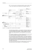
Страница 516: ...A Appendix 516 7UT613 63x Manual C53000 G1176 C160 2 7UT633 B Figure A 7 General diagram 7UT633 panel surface mounting ...
Страница 517: ...A 2 Terminal Assignments 517 7UT613 63x Manual C53000 G1176 C160 2 7UT633 N ...
Страница 518: ...A Appendix 518 7UT613 63x Manual C53000 G1176 C160 2 7UT633 N Figure A 8 General diagram 7UT633 panel surface mounting ...
Страница 519: ...A 2 Terminal Assignments 519 7UT613 63x Manual C53000 G1176 C160 2 7UT635 B ...
Страница 520: ...A Appendix 520 7UT613 63x Manual C53000 G1176 C160 2 7UT635 B Figure A 9 General diagram 7UT635 panel surface mounting ...
Страница 521: ...A 2 Terminal Assignments 521 7UT613 63x Manual C53000 G1176 C160 2 7UT635 N ...
Страница 522: ...A Appendix 522 7UT613 63x Manual C53000 G1176 C160 2 7UT635 N Figure A 10 General diagram 7UT635 panel surface mounting ...
Страница 622: ...A Appendix 622 7UT613 63x Manual C53000 G1176 C160 2 ...
Страница 632: ...Literature 632 7UT613 63x Manual C53000 G1176 C160 2 ...


