


2.3 Restricted Earth Fault Protection
147
7UT613/63x Manual
C53000-G1176-C160-2
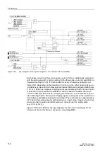
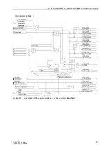
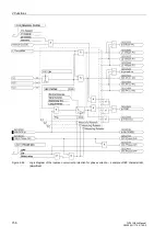
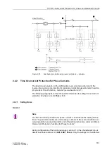
Figure 2-64
Logic diagram of the earth fault protection (simplified)
2.3.3
Setting Notes
General
Note
The first restricted earth fault protection is described in the setting instructions. The pa-
rameter addresses and message numbers of the second restricted earth fault protec-
tion are described at the end of the setting instructions under „Additional Restricted
Earth Fault Protection Functions“.
The restricted earth fault protection can only operate if this function has been set
during configuration of the functional scope (section 2.1.4) under address
113
REF
PROT.
to
Enabled
. If the second restricted earth fault protection is used, it also needs
to be set at address
114
REF PROT. 2
Enabled
. Furthermore, a further 1-phase
measured current input must be assigned to the same side or measuring location
where the starpoint current is to be processed (see section 2.1.4, margin heading „As-
signment of Auxiliary 1-phase Measuring Locations“). The restricted earth fault protec-
tion itself must have been assigned to this side or measuring location (see section
2.1.4, margin heading „Earth Fault Differential Protection“).
The first restricted earth fault protection can be set at address
1301
REF PROT.
to
enabled (
ON
) or disabled (
OFF
); when set to Block relay, the protection function oper-
ates but no trip command is issued.
Block relay
).
Содержание SIPROTEC 7UT613 series
Страница 16: ...Contents 16 7UT613 63x Manual C53000 G1176 C160 2 Literature 631 Glossary 623 Index 633 ...
Страница 30: ...1 Introduction 30 7UT613 63x Manual C53000 G1176 C160 2 ...
Страница 506: ...A Appendix 506 7UT613 63x Manual C53000 G1176 C160 2 7UT633 D E ...
Страница 508: ...A Appendix 508 7UT613 63x Manual C53000 G1176 C160 2 7UT633 P Q ...
Страница 510: ...A Appendix 510 7UT613 63x Manual C53000 G1176 C160 2 7UT635 D E ...
Страница 512: ...A Appendix 512 7UT613 63x Manual C53000 G1176 C160 2 7UT635 P Q ...
Страница 515: ...A 2 Terminal Assignments 515 7UT613 63x Manual C53000 G1176 C160 2 7UT633 B ...
Страница 516: ...A Appendix 516 7UT613 63x Manual C53000 G1176 C160 2 7UT633 B Figure A 7 General diagram 7UT633 panel surface mounting ...
Страница 517: ...A 2 Terminal Assignments 517 7UT613 63x Manual C53000 G1176 C160 2 7UT633 N ...
Страница 518: ...A Appendix 518 7UT613 63x Manual C53000 G1176 C160 2 7UT633 N Figure A 8 General diagram 7UT633 panel surface mounting ...
Страница 519: ...A 2 Terminal Assignments 519 7UT613 63x Manual C53000 G1176 C160 2 7UT635 B ...
Страница 520: ...A Appendix 520 7UT613 63x Manual C53000 G1176 C160 2 7UT635 B Figure A 9 General diagram 7UT635 panel surface mounting ...
Страница 521: ...A 2 Terminal Assignments 521 7UT613 63x Manual C53000 G1176 C160 2 7UT635 N ...
Страница 522: ...A Appendix 522 7UT613 63x Manual C53000 G1176 C160 2 7UT635 N Figure A 10 General diagram 7UT635 panel surface mounting ...
Страница 622: ...A Appendix 622 7UT613 63x Manual C53000 G1176 C160 2 ...
Страница 632: ...Literature 632 7UT613 63x Manual C53000 G1176 C160 2 ...


